EGR cooler of integrated water-removing device

An EGR cooler and water collection technology, applied in the direction of charging system, machine/engine, engine components, etc., can solve the problems of weak automation and poor drainage effect, and achieve strong automation, high degree of automation, and drainage effect Good results

Active Publication Date: 2018-04-20
DONGFENG COMML VEHICLE CO LTD
View PDF7 Cites 5 Cited by
  • Summary
  • Abstract
  • Description
  • Claims
  • Application Information

AI Technical Summary

Problems solved by technology

[0007] The purpose of the present invention is to overcome the defects and problems of poor drainage effect and weak automaticity in the prior art, and provide an EGR cooler with integrated water removal device with good drainage effect and strong automaticity

Method used


Image

  • EGR cooler of integrated water-removing device
  • EGR cooler of integrated water-removing device
  • EGR cooler of integrated water-removing device

Examples


Embodiment 1

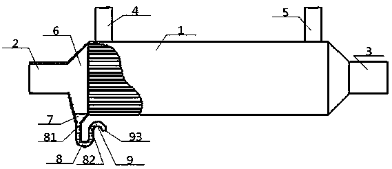
[0036] see Figure 1 to Figure 3 , an EGR cooler with an integrated water removal device, comprising a body 1, an air inlet pipe 2, an air outlet pipe 3, a liquid inlet pipe 4 and a liquid outlet pipe 5, the air inlet pipe 2 communicates with the air outlet pipe 3 through the body 1, The side of the device body 1 communicates with the liquid inlet pipe 4 and the liquid outlet pipe 5; A water collecting funnel 7 with a wide upper part and a narrower lower part is provided at the position, the top of the water collecting funnel 7 communicates with the bottom of the hollow cavity 6, the bottom of the water collecting funnel 7 communicates with the left top port 81 of the U-shaped pipe 8, and the U-shaped The right top port 82 of the pipe 8 communicates with the water outlet 9 , and the left top port 81 and the right top port 82 are both located at the highest point of the U-shaped pipe 8 . Preferably, the top of the water collecting funnel 7 is flush with the bottom of the body ...

Embodiment 2

[0039] Basic content is the same as embodiment 1, the difference is:

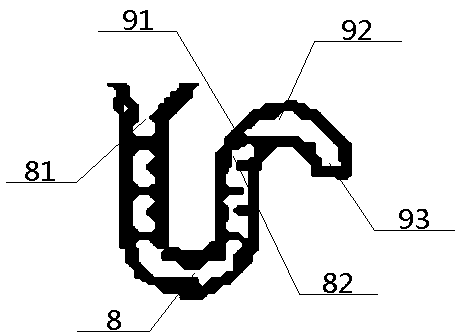
[0040] The water outlet part 9 includes a left bottom port 91, a middle arc portion 92 and a right bottom port 93. The right top port 82 communicates with the right bottom port 93 after passing through the left bottom port 91 and the middle arc portion 92 in turn, and the left bottom port 91 , the right bottom port 93 are all lower than the central arc portion 92 settings.

Embodiment 3

[0042] Basic content is the same as embodiment 1, the difference is:

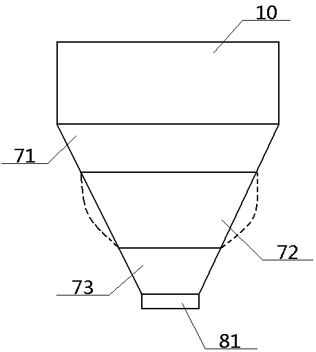
[0043] The above-mentioned water collecting funnel 7 includes an upper cone 71, a middle cone 72 and a lower cone 73, and the upper cone 71, the middle cone 72, and the lower cone 73 are all truncated conical structures with a wide top and a narrow bottom; The top of portion 71 communicates with the bottom of hollow cavity 6, and the bottom of upper cone portion 71 communicates with left top port 81 after passing through middle cone portion 72 and lower cone portion 73 successively. The manufacturing material of middle cone portion 72 is an elastic film, and The thickness of the middle taper portion 72 is greater than the thickness of the upper taper portion 71 and the lower taper portion 73 . Preferably, the top of the water collecting funnel 7 is connected to the bottom of the hollow cavity 6 through a transition part 10, the transition part 10 is a cylindrical structure, and the material of the transitio...


PUM


Abstract

The invention relates to an EGR cooler of an integrated water-removing device. In the EGR cooler of the integrated water-removing device, a gas inlet pipe communicates with a gas outlet pipe through adevice body; the side part of the device body communicates with a liquid inlet pipe and a liquid outlet pipe; the gas inlet pipe communicates with the left end part of the device body through a hollow cavity; a water-collecting funnel with an upper wide part and a lower narrow part is arranged on the part, near the gas inlet pipe, at the bottom of the device body; the top end of the water-collecting funnel communicates with the bottom of the hollow cavity; the bottom end of the water-collecting funnel communicates with the left top port of a U-shaped pipe; the right top port of the U-shaped pipe communicates with the right bottom port of a water outlet part; and the left top port and the right top port are positioned at the highest point of the U-shaped pipe. According to the design, thewater discharge effect is better, the automaticity is higher, the expansivity is higher and the safety is higher.

Description

technical field [0001] The invention relates to an EGR cooler, which belongs to the technical field of automobile engines, in particular to an EGR cooler integrated with a water removal device, which is particularly suitable for improving drainage effect and enhancing automation. Background technique [0002] With the tightening of vehicle emission limits, EGR technology has been gradually applied to engines and has become one of the technical routes to reduce emissions. In particular, the cold EGR scheme also ensures that the intake air temperature and intake air volume are within the required range. In the cold EGR technical solution, the EGR cooler is a key part, which plays the role of cooling the engine exhaust gas to a suitable temperature. The principle is that when the exhaust gas passes through the heat exchanger, it exchanges heat with the engine coolant, thereby reducing the temperature of the exhaust gas. Purpose. Generally, the EGR cooler is only suitable for ...

Claims


Application Information

Patent Timeline
Patent Type & Authority Applications(China)
IPC IPC(8): F02M26/32
CPCF02M26/32
Inventor 安涛徐敏李阳
Owner DONGFENG COMML VEHICLE CO LTD
Why Eureka
Try Eureka