Pumping system and wet spraying machine

A technology of pumping system and wet spraying machine, applied in pipeline systems, pumps, components of pumping devices for elastic fluids, etc., can solve the problems of increased conveying resistance, low pumping efficiency, etc., and reduce material conveying resistance. , Reduce the pumping efficiency, the effect of continuous pumping

Pending Publication Date: 2018-04-20
锦鸡重工(平潭综合实验区)科技有限公司
View PDF0 Cites 0 Cited by
  • Summary
  • Abstract
  • Description
  • Claims
  • Application Information

AI Technical Summary

Problems solved by technology

However, since each delivery cylinder has to go through a repeated process of sucking and pumping materials, the material delivery is interrupted when the material is sucked. On the one hand, the pumping efficiency is low. On the other hand, there are pressure shock waves in the pipeline, which is easy Creates a "water hammer" effect that increases conveying resistance

Method used


Image

  • Pumping system and wet spraying machine
  • Pumping system and wet spraying machine
  • Pumping system and wet spraying machine

Examples


Embodiment Construction

[0030] The present invention will be further described in detail below with reference to the accompanying drawings and specific embodiments, but the protection scope of the present invention is not limited thereby.

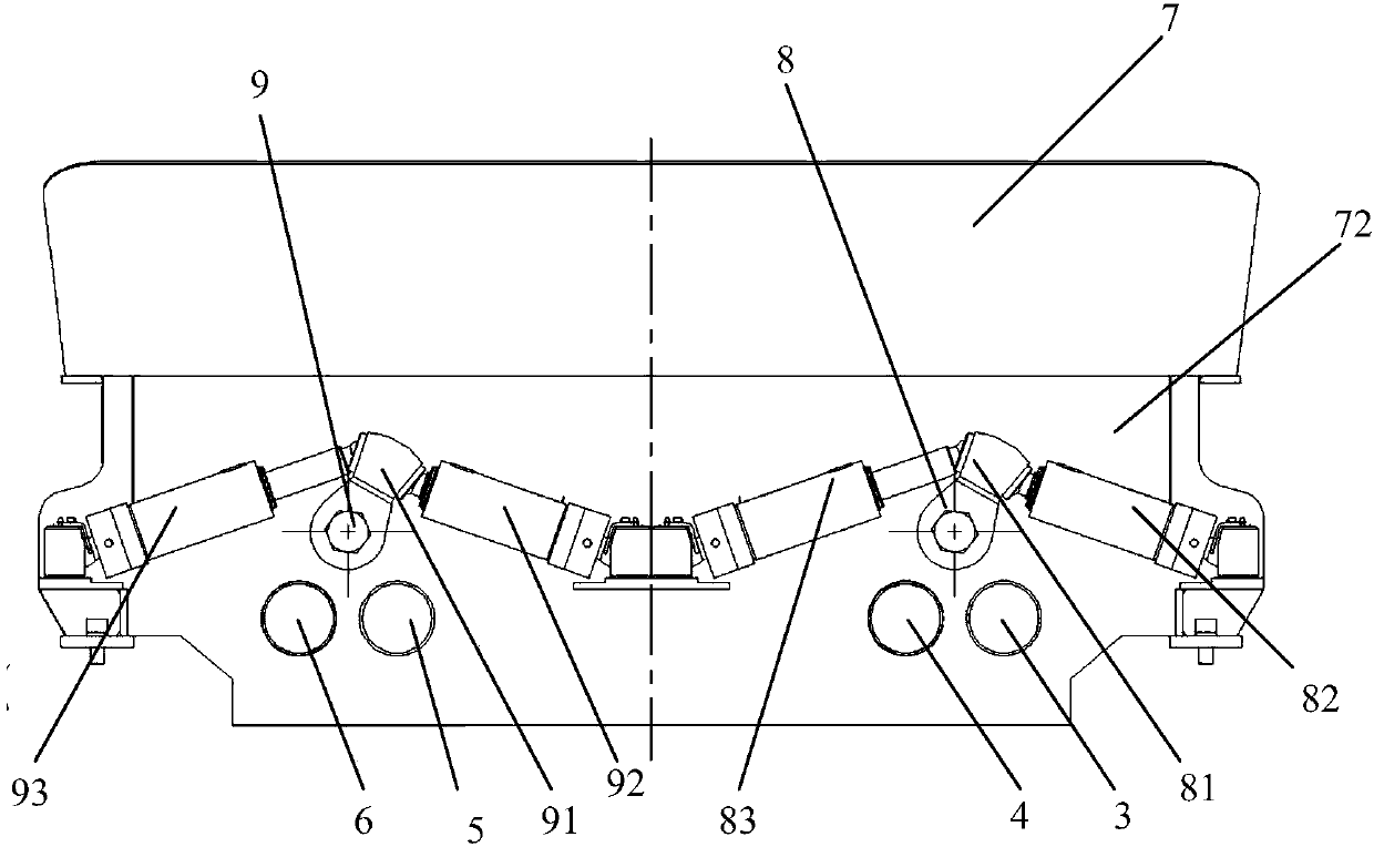
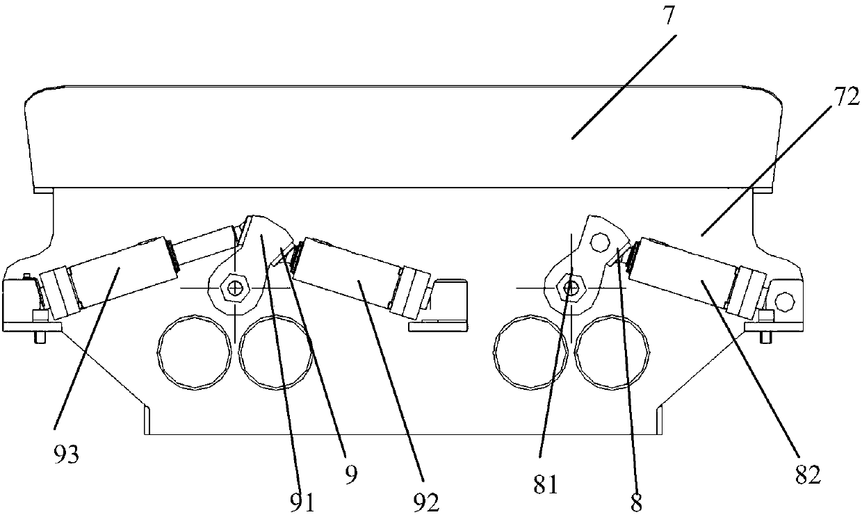
[0031] figure 1 A pumping system 10 of an embodiment of the present invention is schematically shown. figure 2 The first reversing mechanism 8 and the second reversing mechanism 9 of the embodiment of the present invention are schematically shown. image 3 Another structure of the first reversing mechanism 8 in the embodiment of the present invention is schematically shown. Figure 4 Another structure of the second reversing mechanism 9 in the embodiment of the present invention is schematically shown. Figure 5 A third structure of the first reversing mechanism 8 and the second reversing mechanism 9 in the embodiment of the present invention is schematically shown. Image 6 A fourth structure of the first reversing mechanism 8 and the second reversing mechani...


PUM


Abstract

The present invention provides a pumping system, which includes a first distribution valve, a second distribution valve, a first delivery cylinder, a second delivery cylinder, a third delivery cylinder, a fourth delivery cylinder and a box body. The first distributing valve and the second distributing valve are arranged side by side in the box, and the first side of the box is provided with a first discharge port communicated with the first distribution valve and a second discharge port communicated with the second distribution valve. A first reversing mechanism connected with the first distributing valve and a second reversing mechanism connected with the second distributing valve are arranged on the second side of the box body. The first delivery cylinder, the second delivery cylinder, the third delivery cylinder and the fourth delivery cylinder are arranged side by side on the second side of the box body, and the first delivery cylinder and the second delivery cylinder can communicate with the first distribution valve independently, The third delivery cylinder and the fourth delivery cylinder are individually capable of communicating with the second distribution valve. A wet spray machine is also available. Suction and material delivery can be carried out at the same time, so as to avoid reducing pumping efficiency and avoid pressure shock waves in the pipeline.

Description

technical field [0001] The invention belongs to the technical field of construction machinery, and in particular relates to a pumping system and a wet sprayer. Background technique [0002] Most of the conveying equipment for concrete and industrial materials adopts the pumping system of side-by-side double-row piston conveying cylinders. By arranging a switchable distribution valve such as S-pipe valve, skirt valve, C-shaped valve, poppet valve, etc. The materials in each conveying cylinder are alternately pushed to a discharge port, and then pumped to the designated location through the pipeline. When working, one conveying cylinder pumps the material, and the other conveying cylinder sucks the material, so as to realize continuous pumping and improve efficiency. [0003] When there is only one conveying device or only one conveying device is required to deliver concrete or industrial materials to two designated locations through two conveying pipelines, the usual solution...

Claims


Application Information

Patent Timeline
Patent Type & Authority Applications(China)
IPC IPC(8): F04B15/02F04B1/00F04B53/10F04B53/00F17D1/08F17D1/14F17D3/01
CPCF04B15/02F04B1/00F04B53/00F04B53/10F17D1/088F17D1/14F17D3/01
Inventor 林国华
Owner 锦鸡重工(平潭综合实验区)科技有限公司
Why Eureka
Try Eureka