Multi-combination constant flow pump

A technology of constant flow pumps and pump heads, which is applied to pumps, pump components, components of pumping devices for elastic fluids, etc. It can solve the problem of intermittent work of multiple plunger pumps and the difficulty of realizing continuous pumping of multiple plunger pumps To avoid the interruption of work, improve the sealing performance and achieve the effect of continuous pumping

Active Publication Date: 2022-05-13
GUANGZHOU XUEBA SPECIAL EQUIP CO LTD
View PDF12 Cites 0 Cited by
  • Summary
  • Abstract
  • Description
  • Claims
  • Application Information

AI Technical Summary

Problems solved by technology

[0004] However, in the above-mentioned related technologies, when the pumping motors are turned on sequentially, it is easy to cause the interruption of the work of multiple plunger pumps due to the delay of the pumping motors, etc., and it is difficult to realize the continuous pumping of multiple plunger pumps without intermittent

Method used


Image

  • Multi-combination constant flow pump
  • Multi-combination constant flow pump
  • Multi-combination constant flow pump

Examples


Embodiment 1

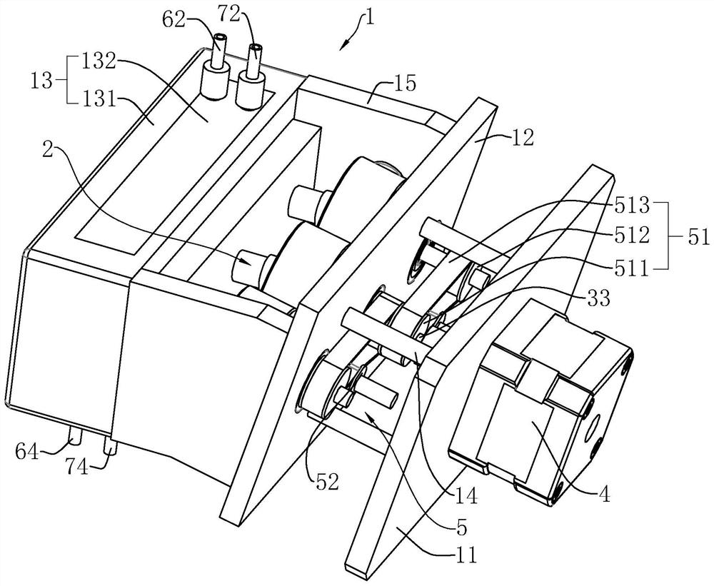
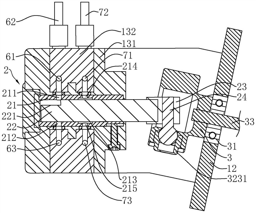
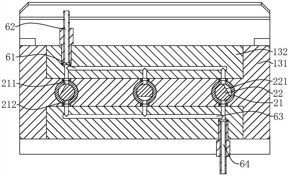
[0044] refer to figure 1 , a multi-combination constant flow pump, including a frame body 1, a pump head 2, a connecting sleeve 3 and a pumping motor 4, a plurality of pump heads 2 are arranged side by side at intervals, and the connecting sleeves 3 correspond to the pump heads 2 one by one. The axes of the pump heads 2 are parallel to each other, and in this embodiment, there are preferably three pump heads 2 . A transmission mechanism 5 for synchronous rotation is arranged between the plurality of connection sleeves 3 , and the pumping motor 4 drives the plurality of connection sleeves 3 to rotate synchronously to control the plurality of pump heads 2 to realize non-intermittent continuous pumping of liquid.

[0045] The frame body 1 includes a motor bracket 11 for installing the pumping motor 4, a connecting sleeve bracket 12 for installing the connecting sleeve 3, a pump head bracket 13 for installing the pump head 2, the motor bracket 11 and the connecting sleeve bracket ar...

Embodiment 2

[0073] combine Figure 5 with Image 6 , a multi-combination constant flow pump. The difference from Embodiment 1 is that the fixed frame 131 includes a single pump frame 1311 corresponding to the pump head 2, and the adjacent single pump frames 1311 are detachably connected. The specific connection mode between two single pump frames 1311 is that two adjacent single pump frames 1311 are respectively provided with socket slots 81 and socket blocks 82 on the two side walls close to each other, and the socket blocks 82 are inserted into the socket slots. 81 and connected by bolt compression.

[0074] The connection sleeve support 12 includes a single sleeve frame 121 corresponding to the connection sleeve 3 one by one, and the adjacent single sleeve frames 121 are detachably connected. The specific connection mode between two adjacent single sleeve frames 121 is that one single sleeve The side wall of the frame 121 is provided with a clamping groove 91, the clamping groove 91 ...


PUM


Abstract

The invention discloses a multi-combination constant flow pump, and relates to the field of constant flow pumps, the multi-combination constant flow pump comprises a frame body, pump heads, pumping motors and connecting sleeves in one-to-one correspondence with the pump heads, the pump heads and the pumping motors are fixedly arranged on the frame body, and the number of the pump heads is n; the pump head comprises a cylinder barrel and a plunger, one end of the plunger is in sliding fit in the cylinder barrel, and a tangent plane is arranged on the peripheral wall of the end, located in the cylinder barrel, of the plunger; a front liquid inlet and a front liquid outlet are formed in the cylinder barrel; the end, away from the cylinder barrel, of the plunger is connected with a plunger base, plunger pin shafts are arranged on the plunger base, connecting sleeves in one-to-one correspondence with the plunger pin shafts are rotationally matched with the frame body, angle support bearings are installed in the connecting sleeves, the plunger pin shafts are connected with the angle support bearings, and an output shaft of the pumping motor is coaxially fixed to one connecting sleeve. A transmission mechanism used for driving the multiple connecting sleeves to rotate synchronously is arranged between the multiple connecting sleeves. The constant flow pump has the effect of achieving non-intermittent continuous pumping.

Description

technical field [0001] The invention relates to the field of constant flow pumps, in particular to a multi-combination constant flow pump. Background technique [0002] Constant flow pumps are widely used in the fields of medicine, chemical industry, and environmental protection because of their precision, durability, and stable delivery flow. [0003] In the related art, the plunger pump adjusts its single filling volume by setting a filling volume adjustment device, but the adjustment range of this adjustment method is limited. When the filling volume is large, it is still necessary to set multiple plungers pump, and control the opening and closing of the pumping motor, so that after one of the plunger pumps absorbs liquid, the other plunger pump is turned on to achieve the preset filling volume. [0004] However, in the above-mentioned related technologies, when the pumping motors are turned on sequentially, it is easy to cause interruptions in the operation of multiple ...

Claims


Application Information

Patent Timeline
Patent Type & Authority Applications(China)
IPC IPC(8): F04B17/03F04B23/06F04B13/00F04B53/16F04B53/14
CPCF04B17/03F04B23/06F04B13/00F04B53/162F04B53/14
Inventor 李旭伟
Owner GUANGZHOU XUEBA SPECIAL EQUIP CO LTD
Why Eureka
Try Eureka