Supercharge Your Innovation With Domain-Expert AI Agents!

Magnetic levitation compressor structure

A compressor and magnetic levitation technology, applied in mechanical equipment, machines/engines, liquid fuel engines, etc., can solve the problems of complex processing technology, axial displacement of shaft sleeves, increased material costs, etc., and achieve simple and compact structure. Good effect, the effect of reducing processing time and cost

Pending Publication Date: 2018-04-20
NANJING CIGU TECH CORP LTD
View PDF8 Cites 6 Cited by
  • Summary
  • Abstract
  • Description
  • Claims
  • Application Information

AI Technical Summary

Problems solved by technology

[0003] After the impeller and balance disc in the existing magnetic levitation compressor are fixed, when it is necessary to adjust the detection gap of the axial displacement sensor and the impeller gap, the balance disc and impeller on the rotor need to be removed, and then go to the lathe for processing to achieve the required gap After installation is required, such repeated size adjustments will cause the rotor to be positioned as a reference, and the shaft sleeve and sealing ring on the rotor will have axial displacement, and there are too many parts on the rotor, and each part has its own tolerance size. All assembled on the rotor, there will be a certain cumulative tolerance, and the more parts assembled on the rotor, the more complicated the processing process will be, the parts may need lathe processing, grinding machine processing, and fitter, the longer the processing time , the number of parts increases, and the cost of materials increases

Method used


Image

  • Magnetic levitation compressor structure
  • Magnetic levitation compressor structure
  • Magnetic levitation compressor structure

Examples


Embodiment Construction

[0017] The present invention will be further described below in conjunction with the accompanying drawings.

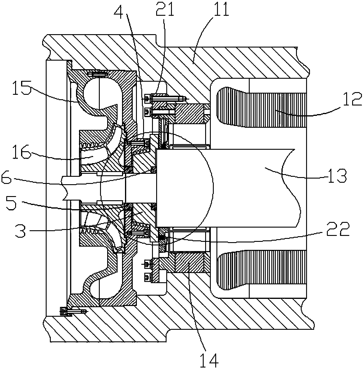
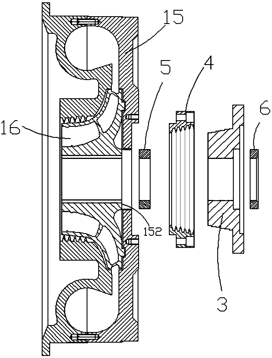
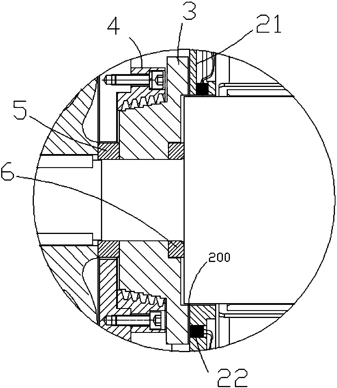
[0018] Such as Figure 1 to Figure 4 , the present invention discloses a magnetic levitation compressor structure, including a casing 11, a stator 12, a rotor 13, a magnetic bearing 14, a volute 15, an impeller 16, a sensor bracket 21 and an axial displacement sensor 22, and the stator 12 is fixed to the casing 11 Inside, the rotor 13 is installed in the stator 12, and the rotor 13 is rotatably supported in the casing 11 through the magnetic bearing 14, the sensor bracket 21 is fixed on the magnetic bearing 14, the axial displacement sensor 22 is arranged on the sensor bracket 21, and the impeller 16 It is fixedly connected with the rotor 13 , the volute 15 is fixed on the casing 11 , and the impeller 16 is arranged in the volute 15 . It also includes a balance disc 3, a seal ring 4, an impeller gap adjustment ring 5 and an axial gap adjustment ring 6, the balance dis...


PUM


Abstract

The invention discloses a magnetic levitation compressor structure. A stator is fixed in a machine shell. A rotor is arranged in the stator in a penetrating mode. The rotor is rotationally supported in the machine shell through a magnetic bearing. A sensor holder is fixed on the magnetic bearing. An axial displacement sensor is arranged on the sensor holder. An impeller is fixedly connected with the rotor. A volute is fixed on the machine shell. The impeller is arranged in the volute. A balance disk, an impeller clearance adjustment ring, and an axial clearance adjustment ring are all arrangedon the rotor in a sleeving mode. The impeller clearance adjustment ring, the balance disk, and the axial clearance adjustment ring are all axially positioned on the step surface of the rotor throughthe impeller. An axial test clearance is formed between the right end surface of the balance disk and the left end surface of the sensor holder. A sealing ring is fixed on the volute. A ventilation clearance is formed between the sealing ring and the balance disk. The magnetic levitation compressor structure is impact, convenient to arrange, the clearance between the balance disk and the axial displacement sensor and the clearance between the impeller and the volute are easy to adjust, and sealing effects are good.

Description

Technical field: [0001] The invention relates to a magnetic levitation compressor structure. Background technique: [0002] The impeller pressure ratio of the compressor is generally relatively high, which will cause a large axial force on the compressor rotor. In order to reduce the load on the thrust bearing, a balance plate structure is generally installed on the rotor to balance part of the axial force. . For the magnetic levitation compressor, a balance disc is also set for the consideration of reducing the axial magnetic bearing load. [0003] After the impeller and balance disc in the existing magnetic levitation compressor are fixed, when it is necessary to adjust the detection gap of the axial displacement sensor and the impeller gap, the balance disc and impeller on the rotor need to be removed, and then go to the lathe for processing to achieve the required gap After installation is required, such repeated size adjustments will cause the rotor to be positioned a...

Claims


Application Information

Patent Timeline
Patent Type & Authority Applications(China)
IPC IPC(8): F04D25/06F04D29/051F04D29/058F04D29/08F04D29/42
CPCF04D25/0606F04D29/051F04D29/058F04D29/083F04D29/4206
Inventor 包金哲林英哲吴立华董继勇
Owner NANJING CIGU TECH CORP LTD
Features
  • R&D
  • Intellectual Property
  • Life Sciences
  • Materials
  • Tech Scout
  • Unparalleled Data Quality
  • Higher Quality Content
  • 60% Fewer Hallucinations
Learn More