Supercharge Your Innovation With Domain-Expert AI Agents!

Inflow structure

A technology of inflow and inflow holes, which is applied to parts of pumping devices for elastic fluids, non-variable pumps, pump components, etc., can solve problems such as difficult to control gaps, manufacturing errors, etc., to ensure consistency performance, maintenance of design performance, and the effect of maximum design performance

Inactive Publication Date: 2020-06-23
汤秉辉
View PDF8 Cites 0 Cited by
  • Summary
  • Abstract
  • Description
  • Claims
  • Application Information

AI Technical Summary

Problems solved by technology

[0005] The general practice is only to require the components to be molded as precisely as possible to reduce the gap between the inlet hole and the impeller. However, in commercial production, the components such as the impeller and the casing are assembled on the production line. The molded components There are some manufacturing errors in itself, plus the errors of subsequent assembly, it is difficult to control the gaps produced every time to be the same small

Method used


Image

  • Inflow structure
  • Inflow structure
  • Inflow structure

Examples


Embodiment Construction

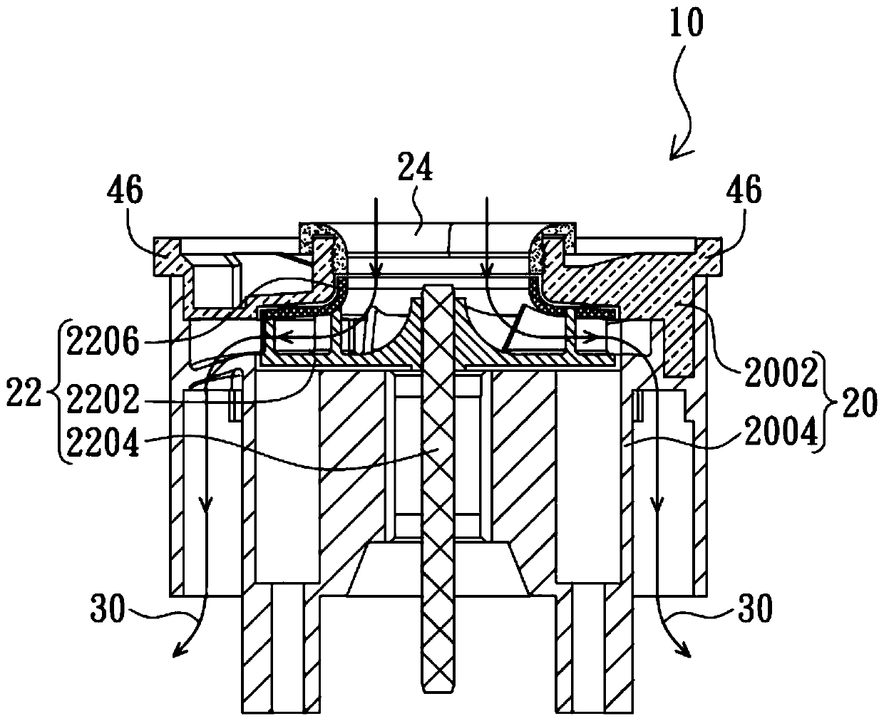
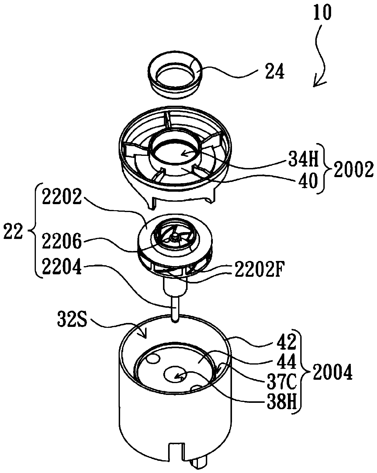
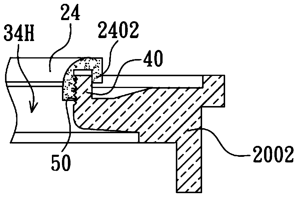
[0023] Specific structural and functional details disclosed herein are representative only and for purposes of describing example embodiments of the present invention. This invention may, however, be embodied in many alternative forms and should not be construed as limited to only the embodiments set forth herein.

[0024] In describing the present invention, it is to be understood that the terms "central", "lateral", "upper", "lower", "left", "right", "vertical", "horizontal", "top", The orientation or position indicated by "bottom", "inner", "outer" and so on are based on the orientation or positional relationship shown in the drawings, which are only for the convenience of describing the present invention and simplifying the description, rather than indicating or implying the referred device Or components must have a particular orientation, be constructed and operate in a particular orientation and therefore should not be construed as limiting the invention. In addition, t...


PUM


Abstract

A diversion structure includes: a shell, an impeller unit, and a flow guiding ring joint. The shell is provided with a flow inlet hole, an accommodating space and a shaft hole. The impeller unit includes an impeller, a driving shaft, and a flow guiding plate inlet. The impeller fixedly sleeves the driving shaft and is placed in the accommodating space. The driving shaft is stretched into the shafthole. The flow guiding plate inlet is correspondingly matched with the flow inlet hole. The flow guiding ring joint sleeves the flow inlet hole so that the edge of the flow guiding ring joint is adjacent to the edge of the flow guiding plate inlet. Fluid, generated by rotation of the impeller, flows through the flow inlet hole and passes through the flow guiding plate inlet, and then enters a main fluid generatrix of rotation of the impeller. By means of the structure, the intermittent reflux disturbance between the flow guiding plate inlet and the flow guiding ring joint of the fluid is reduced.

Description

technical field [0001] The invention relates to an inflow structure, in particular to an inflow structure used in a fluid machine to reduce fluid backflow disturbance. Background technique [0002] Fluid machinery is widely used, such as vacuum cleaners, air compressors, water pumps, etc., to solve the needs of fluids such as air and water for work in life. However, machinery inevitably has tolerances or gaps, especially for machinery with rotation or other motions, gaps must exist. [0003] During the diversion process of these fluid machines, it is hoped to reduce the proportion of fluid escape or backflow disturbance, so as to make the diversion effect better. In theory, the commercial sales of vacuum cleaners emphasize strong suction. If the air leakage is not reduced, the goal of strong suction will not be achieved at all. [0004] Most fluid machines generate fluid flow through the rotation of the impeller. The impeller will be assembled in an inflow structure. The t...

Claims


Application Information

Patent Timeline
Patent Type & Authority Patents(China)
IPC IPC(8): F04D29/22F04D29/28F04D29/42
CPCF04D29/22F04D29/28F04D29/42F04D29/4213
Inventor 汤秉辉
Owner 汤秉辉
Features
  • R&D
  • Intellectual Property
  • Life Sciences
  • Materials
  • Tech Scout
  • Unparalleled Data Quality
  • Higher Quality Content
  • 60% Fewer Hallucinations
Learn More