Axial flow fan capable of achieving accurate zero clearance

An axial flow fan and clearance technology, applied in mechanical equipment, machines/engines, liquid fuel engines, etc., can solve problems such as deformation, aggravating the overall performance of the fan, and low efficiency

Pending Publication Date: 2018-04-20
ZHEJIANG SHANGFENG SPECIAL BLOWER IND CO LTD
View PDF7 Cites 0 Cited by
  • Summary
  • Abstract
  • Description
  • Claims
  • Application Information

AI Technical Summary

Problems solved by technology

[0002] The axial flow fan is composed of impeller, motor and fan cylinder. As a rotating part, the impeller has a certain gap with the inner wall of the fan cylinder. The larger the gap, the lower the efficiency of the fan, the greater th

Method used


Image

  • Axial flow fan capable of achieving accurate zero clearance
  • Axial flow fan capable of achieving accurate zero clearance

Examples


Embodiment 1

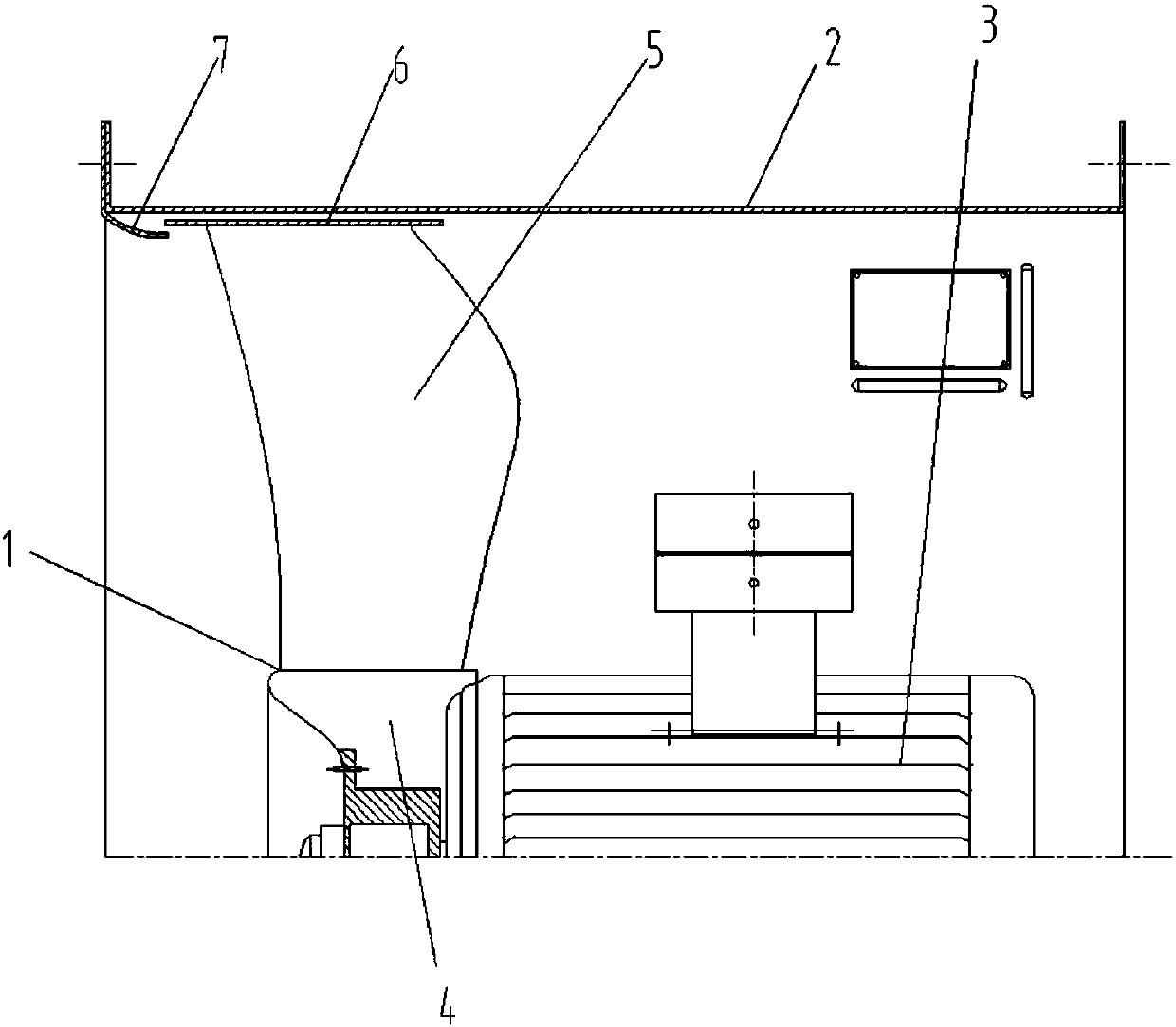
[0010] Embodiment one: if figure 1 As shown, the present invention discloses a quasi-zero-gap axial flow fan, including an impeller 1, an air cylinder 2 and a motor 3, and the impeller 1 includes a hub 4 connected to the output shaft of the motor 3 and evenly distributed on the periphery of the hub 4 Several blades 5 on the surface, as mentioned above, are basically consistent with the structure of the existing common axial flow fan. The tip partition 6 is cylindrical, and its thickness matches the width of the blade 5, that is, the projected width of the blade 5 in the axial direction of the impeller 1 is approximately the same, and the cylindrical outer wall of the wing tip partition 6 is consistent with the inner wall 2 of the air duct. are parallel to each other, and the gap is usually 5-10 mm; the flange of the air inlet of the air duct 2 is provided with a collector 7, the collector 7 is bell-shaped, and its small head is facing the wingtip partition 6, so Described win...

Embodiment 2

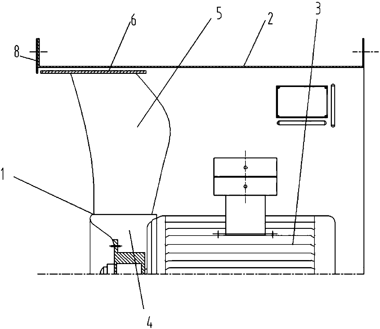
[0011] Embodiment two: if figure 2 As shown, the air inlet flange of the air cylinder 2 is provided with an inlet baffle 8 to replace the collector 7, and the inlet baffle 8 is fixed on the flange of the air cylinder 2 and extends toward the center of the air cylinder 2. , the end of the wingtip partition 6 towards the air inlet is level with the inner end of the inlet partition 8, and the gap between the wingtip partition 6 and the inlet partition 8 is 2-5 mm. Since the manufacture and installation of the inlet partition 8 is more convenient, the cost is lower, and the effect similar to that of the current collector 7 can be achieved, so it is more widely used in actual production occasions.


PUM


Abstract

The invention discloses an axial flow fan capable of achieving an accurate zero clearance. The axial flow fan comprises an impeller, a wind barrel and a motor, wherein the impeller comprises a hub connected to an output shaft of the motor, and a plurality of blades uniformly distributed on the peripheral surface of the hub; wingtips of the blades are provided with wingtip partitions; a current collector is arranged on an air inlet flange of the wind barrel; and the ends, facing the current collector, of the wingtip partitions stretch into the place between the current collector and the inner wall of the wind barrel. According to the axial flow fan, a combination of the wingtip partitions and the current collector is adopted, a zero clearance is formed between the impeller tip and the innerwall of the wind barrel, the functions of reducing noise, increasing pressure, reducing flow loss, improving device reliability and prolonging the operation life cycle of the device are achieved, operation pressure of the device is increased, blade vibration is reduced, the service life of the impeller is prolonged, the surge problem is solved, and the operation working area of the device is expanded.

Description

technical field [0001] The invention relates to an axial flow fan model, in particular to a quasi-zero gap model between an impeller and an air cylinder in an axial flow fan. Background technique [0002] The axial flow fan is composed of impeller, motor and fan cylinder. As a rotating part, the impeller has a certain gap with the inner wall of the fan cylinder. The larger the gap, the lower the efficiency of the fan, the greater the noise, and the air volume and pressure. The lower it is, when the speed is high, the blades on the impeller will have a certain amount of deformation, which will aggravate the deterioration of the overall performance of the fan. With the rapid development of my country's economy and industry, there is an urgent need for a high-efficiency and low-noise axial flow fan to be applied to various ventilation and fire-fighting occasions. Contents of the invention [0003] In order to overcome the above defects, the present invention aims to provide ...

Claims


Application Information

Patent Timeline
IPC IPC(8): F04D29/66F04D29/38F04D29/00
CPCF04D29/002F04D29/388F04D29/666
Inventor 蒋洪涛邵准远胡伟锋侯金亮
Owner ZHEJIANG SHANGFENG SPECIAL BLOWER IND CO LTD
Why Eureka
Try Eureka