
Control arm for injection valve

A control arm and injection valve technology, applied in the control arm field, can solve the problems of reducing the service life of the bushing, corrosion, etc., and achieve the effect of strengthening the structural strength

Inactive Publication Date: 2018-04-20
SUZHOU RSHTEK ELECTRICAL EQUIP CO LTD
View PDF0 Cites 0 Cited by
  • Summary
  • Abstract
  • Description
  • Claims
  • Application Information

AI Technical Summary

Problems solved by technology

[0003] The control arm with the bushing installed may be corroded by the outside in the long run due to the rubber parts used in the bushing, which will reduce the service life of the bushing

Method used


Image

  • Control arm for injection valve
  • Control arm for injection valve
  • Control arm for injection valve

Examples


Embodiment Construction

[0027] The specific implementation manners of the present invention will be further described in detail below in conjunction with the accompanying drawings and embodiments. The following examples are used to illustrate the present invention, but are not intended to limit the scope of the present invention.

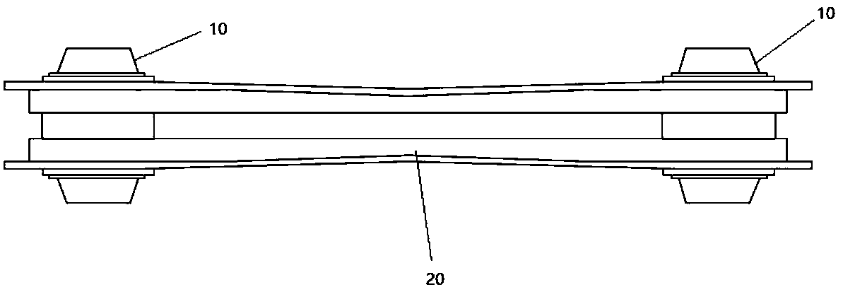
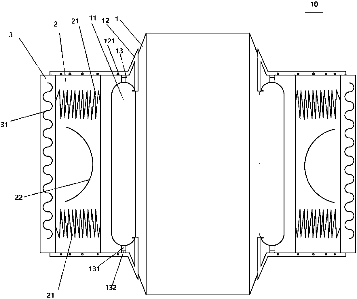
[0028] see Figure 1 to Figure 3 , the control arm for an injection valve according to a preferred embodiment of the present invention includes an arm body 20, and bushes 10 arranged at both ends of the arm body 20,

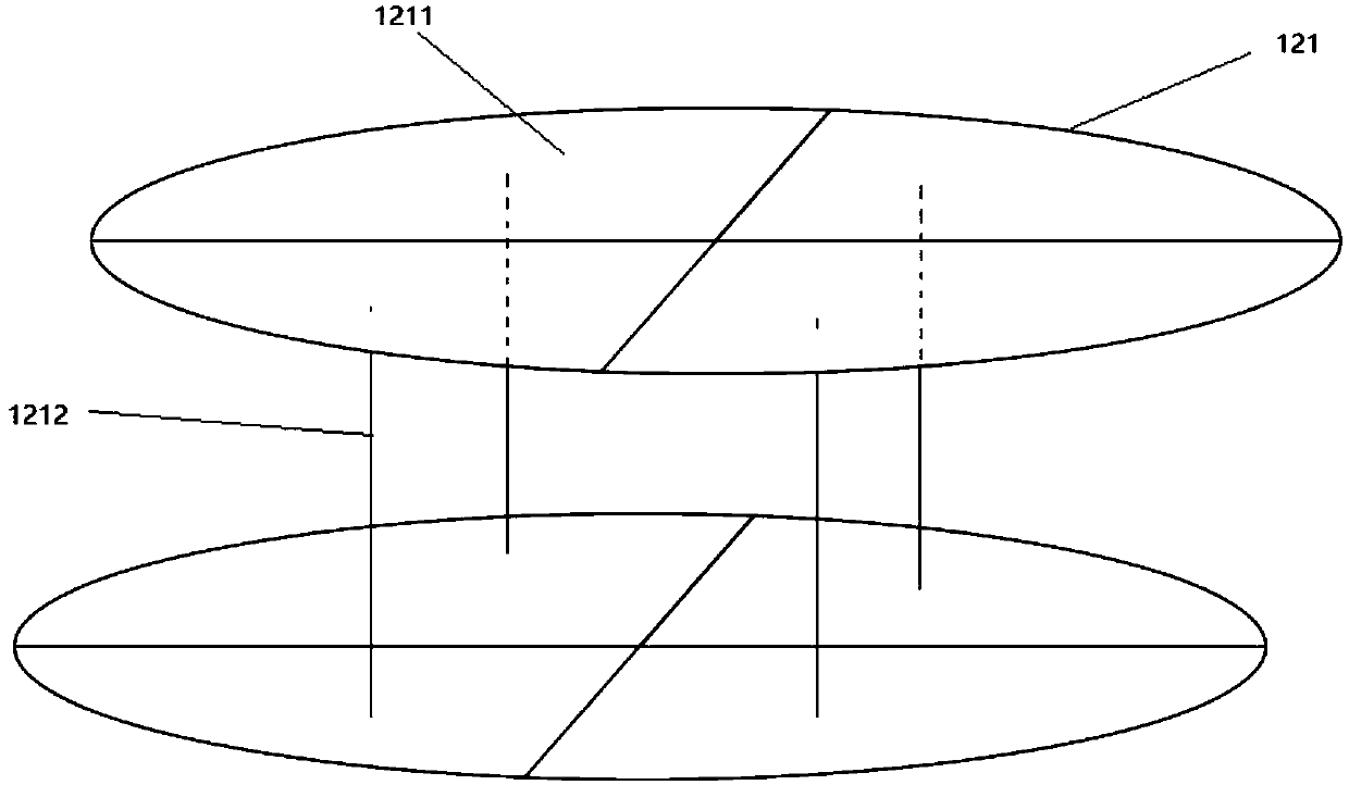
[0029] The bushing 10 includes an inner liner 1, a rubber ring 2 and an outer liner 3, the rubber ring 2 is arranged between the inner liner 1 and the outer liner 3; There are a plurality of hollow cavities 11 uniformly distributed along the cross-section of the liner 1, and an air inlet pipe 13 is connected to the upper and lower ends of the cavity 11, and the air inlet pipe 13 is connected to the outside of the liner pipe 1; The upper and lower ends of th...


PUM


Abstract

The present invention designs a control arm for an injection valve, which includes an arm body and bushes arranged at both ends of the arm body. The bushing includes an inner liner, a rubber ring and an outer liner. The rubber ring is arranged on Between the inner liner and the outer liner; the inside of the inner liner is provided with a plurality of hollow cavities uniformly distributed along the cross section of the inner liner, and the upper and lower ends of the cavity are connected with an air inlet pipe, The air inlet pipe is connected to the outside of the lining pipe; the upper and lower ends of the cavity are connected to one end of an air delivery pipe, and the other end of the air delivery pipe extends to the outside of the inner lining pipe and is transversely connected to the inner lining pipe. On the pipe, the rubber ring and the outer liner; the air pipe is provided with a plurality of exhaust holes. The device can output the gas in the cavity to the annulus of the bushing through the exhaust hole when the cavity provided inside is squeezed, so as to clean the annulus of the bushing.

Description

technical field [0001] The invention relates to a control arm, in particular to a control arm for an injection valve. Background technique [0002] The control arm, also known as the swing arm, acts as a guiding and force transmitting element. In the dispensing device, the control arm is used as a device for power transmission of the injection valve, and its main function is to control the movement of the injection valve according to a certain trajectory. The ball valve is an element used to connect the control arm to the injection valve. [0003] The control arm with the bushing installed may be corroded by the outside for a long time due to the use of rubber parts in the bushing, which will reduce the service life of the bushing. [0004] In view of the above-mentioned defects, the designer actively researches and innovates in order to create a control arm for injection valves with a new structure that can automatically clean the surface of the bushing, so that it has mo...

Claims


Application Information

Patent Timeline
IPC IPC(8): F16K51/00F16C33/04F16L9/14F16L57/02F16F7/108B08B5/02
CPCF16K51/00B08B5/02F16C33/04F16F7/108F16L9/14F16L57/02
Inventor 吴兴理
Owner SUZHOU RSHTEK ELECTRICAL EQUIP CO LTD
Learn More