Air guide assembly and refrigerator thereof

A technology of air guide components and air guide outlets, which is applied in household refrigeration devices, lighting and heating equipment, household appliances, etc. It can solve the problems of affecting the aesthetic effect, high temperature, and easy blocking of the air outlet by stored objects, so as to achieve beautiful and simple structure , increase cooling efficiency, improve the effect of cooling performance

Active Publication Date: 2018-04-20
HAIER SMART HOME CO LTD
View PDF6 Cites 10 Cited by
  • Summary
  • Abstract
  • Description
  • Claims
  • Application Information

AI Technical Summary

Problems solved by technology

[0002] Refrigerators are indispensable household appliances in people's daily life. In the existing air-cooled refrigerators, the air outlets of the air ducts in the freezer or refrigerator are all located at the back of the compartment, and the position of the air outlet after opening the refrigerator door It can be seen that it affects the overall aesthetic effect, and it is easy to block the air outlet when placing storage in the compartment, which affects the cooling efficiency of the compartment; at the same time, in order to increase the storage capacity of the refrigerator, there are many bottle holders on the refrigerator door. Because the air outlet of the existing air duct is set on the back of the liner, the cold air blown out is far away from the bottle holder, and the cooling effect on the storage in the bottle holder is not obvious, making the temperature of the bottle holder relatively high, which is not conducive to the refrigeration of food storage

Method used


Image

  • Air guide assembly and refrigerator thereof
  • Air guide assembly and refrigerator thereof
  • Air guide assembly and refrigerator thereof

Examples


Embodiment Construction

[0015] In order to enable those skilled in the art to better understand the technical solutions in the present invention, the technical solutions in the embodiments of the present invention will be clearly and completely described below in conjunction with the drawings in the embodiments of the present invention. Obviously, the described The embodiments are only some of the embodiments of the present invention, not all of them. Based on the embodiments of the present invention, all other embodiments obtained by persons of ordinary skill in the art without making creative efforts shall fall within the protection scope of the present invention.

[0016] In the description of the present invention, it should be understood that the orientation or positional relationship indicated by the terms "upper", "lower", "front", "rear", "left", "right" etc. are based on those shown in the accompanying drawings. Orientation or positional relationship is only for the convenience of describing...


PUM


Abstract

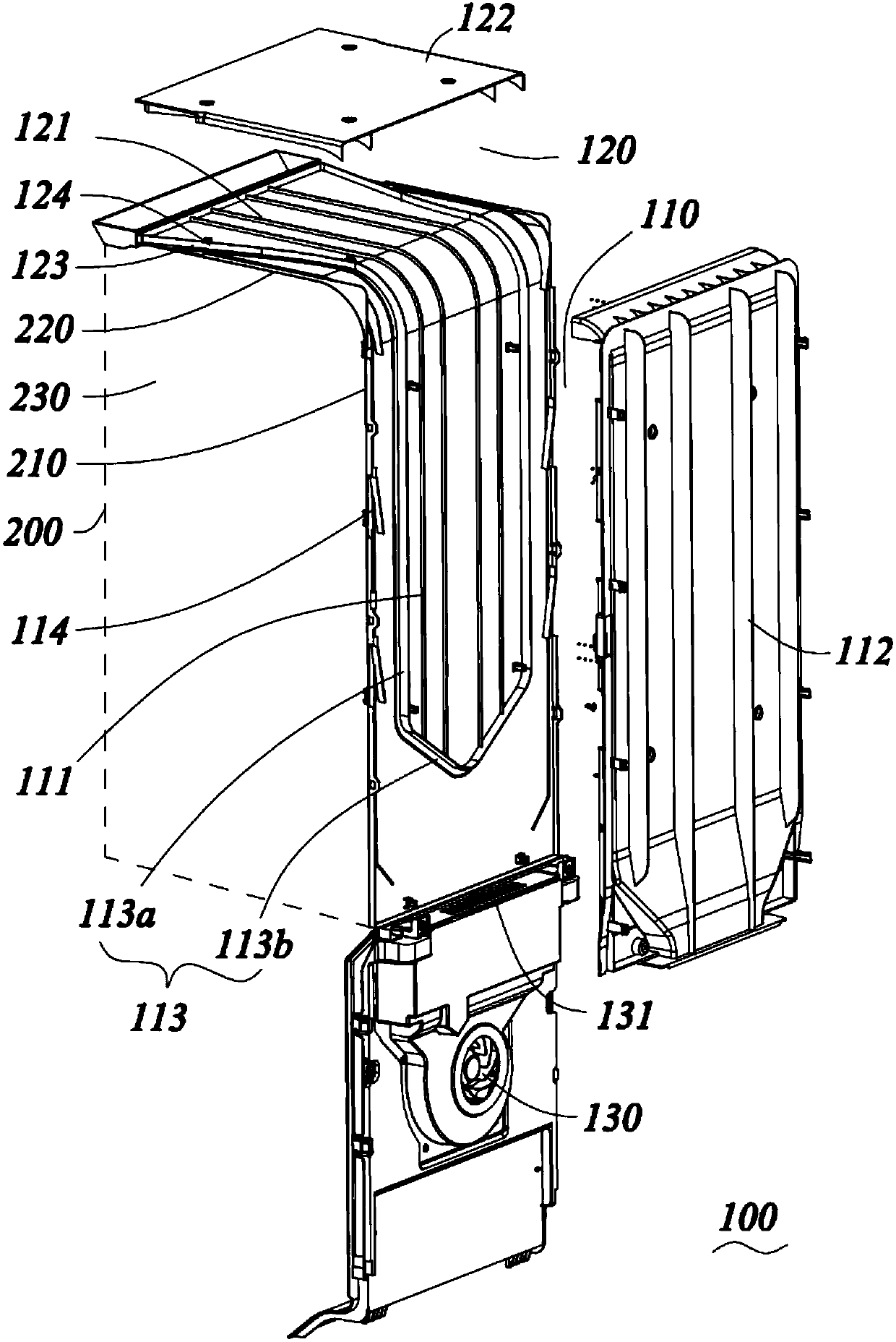
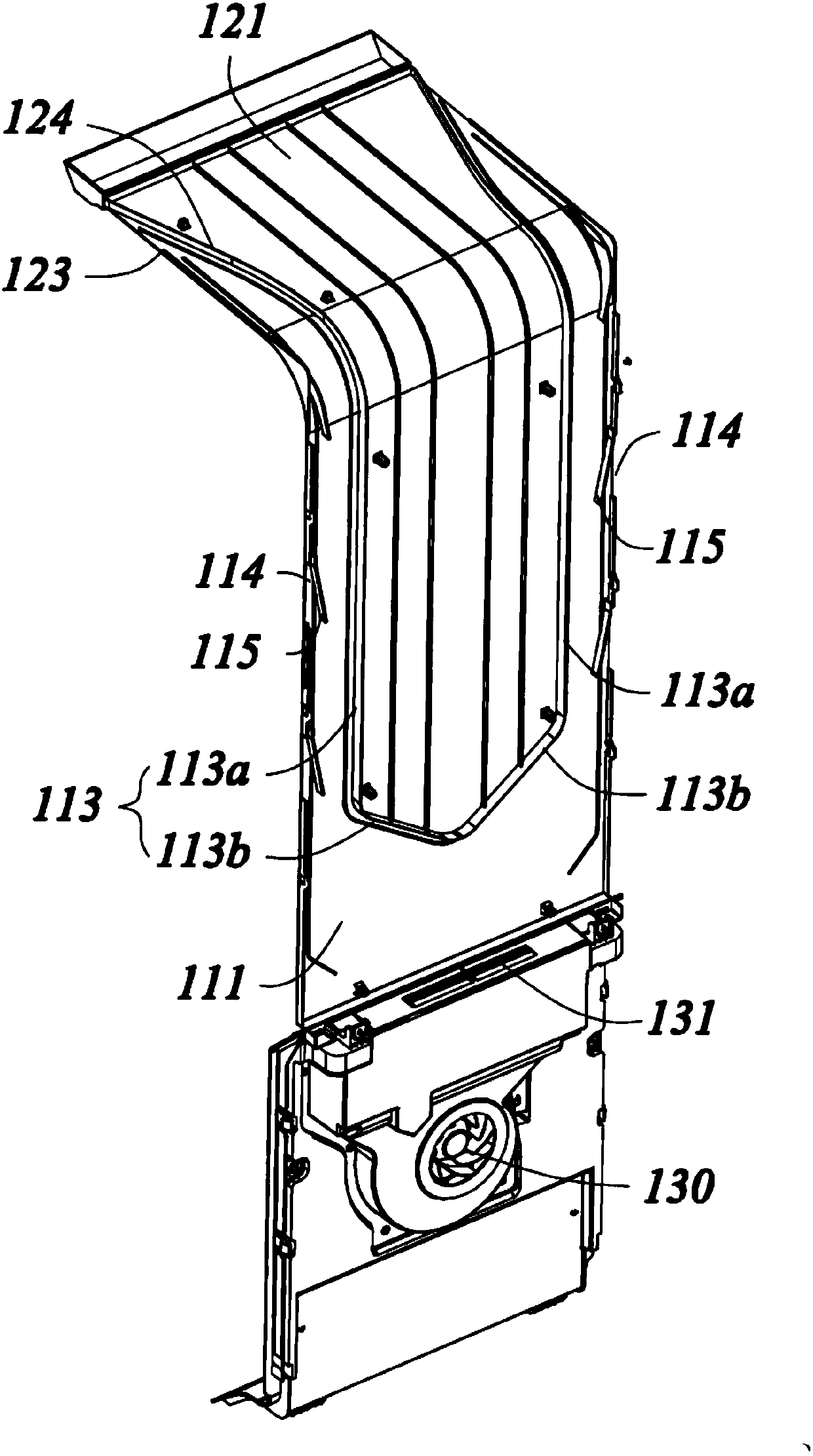
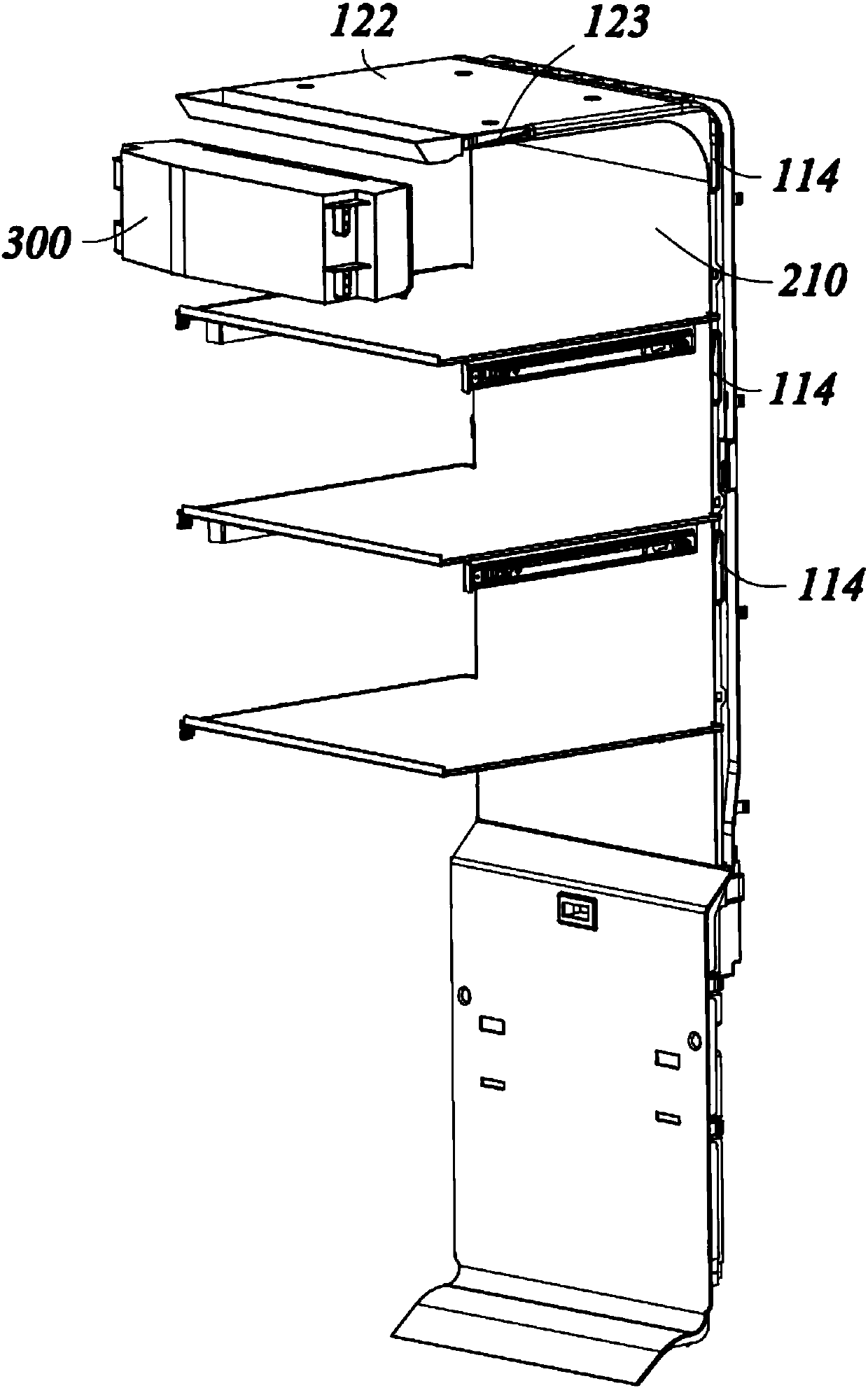
The invention provides an air guide assembly supplying air to a refrigerator chamber and a refrigerator of the air guide assembly. The refrigerator comprises at least one refrigeration chamber, a doorbody for opening and closing the chamber and an evaporator supplying cold to the interior of the chamber. The chamber is provided with a rear wall, a top wall and side walls, and a bottle seat is arranged on the door body. The air guide assembly comprises a first air flue, a second air flue and a fan communicating with the first air flue through an air guide opening, wherein the first air flue communicates with the second air flue. The first air flue is arranged in a manner of extending in the up-and-down direction of the rear wall, and first air outlets supplying air to the chamber are formed in the left side and the right side of the first air flue. The second air flue is connected to the upper end of the first air flue and is arranged in a manner of extending in the front-and-back direction of the top wall. Second air outlets are formed in the left side and the right side of the second air flue, and cold air in the second air flue can be blown into the door body and the bottle seattowards the lateral front portion. The problem that the temperature difference of the door body and the bottle seat is relatively too high large in the prior art is effectively solved, the refrigeration efficiency is improved, and the refrigeration performance of the refrigerator is improved.

Description

technical field [0001] The invention belongs to the technical field of household appliances, and in particular relates to an air guide assembly for supplying air to a compartment of a refrigerator. Background technique [0002] Refrigerators are indispensable household appliances in people's daily life. In the existing air-cooled refrigerators, the air outlets of the air ducts in the freezer or refrigerator are all located at the back of the compartment, and the position of the air outlet after opening the refrigerator door It can be seen that it affects the overall aesthetic effect, and it is easy to block the air outlet when placing storage in the compartment, which affects the cooling efficiency of the compartment; at the same time, in order to increase the storage capacity of the refrigerator, there are many bottle holders on the refrigerator door. Because the air outlet of the existing air duct is set on the back of the liner, the cold air blown out is far away from the...

Claims


Application Information

Patent Timeline
Patent Type & Authority Applications(China)
IPC IPC(8): F25D17/06F25D23/04
CPCF25D17/062F25D23/04F25D2317/063F25D2317/0664
Inventor 贾文娟任树飞窦金强王萌
Owner HAIER SMART HOME CO LTD
Why Eureka
Try Eureka