Ceramic drying equipment

A technology for drying equipment and ceramics, applied in the direction of drying, drying, and drying of ceramic products, can solve the problems of poor hot air fluidity, insufficient drying, affecting drying, etc., to increase air flow, improve The effect of drying

Pending Publication Date: 2018-04-20
FOSHAN WANSHAN ENVIRONMENTAL PROTECTION TECH CO LTD
View PDF8 Cites 0 Cited by
  • Summary
  • Abstract
  • Description
  • Claims
  • Application Information

AI Technical Summary

Problems solved by technology

The existing ceramic drying equipment has the following problems: after the hot air is transported into the drying box and contacts the ceramic products, the hot air will be cooled down to lower temperature air, and the cooled air will gather in the drying box. At the bottom, the accumulated lower temperature air will affect the circulation of the air in the drying box, making the fluidity of the newly delivered hot air worse and affecting the drying; at the same time, the lower temperature air gathers in the drying box The bottom of the ceramic product also makes the bottom part of the ceramic product insufficiently dried; the above problems all affect the effect of the ceramic drying to a certain extent, and have a certain impact on the quality of the ceramic.

Method used


Image

  • Ceramic drying equipment
  • Ceramic drying equipment
  • Ceramic drying equipment

Examples


Embodiment Construction

[0023] In order to make the object, technical solution and effect of the present invention more clear and definite, the present invention will be further described in detail below with reference to the accompanying drawings and examples. It should be understood that the specific embodiments described here are only used to explain the present invention, not to limit the present invention.

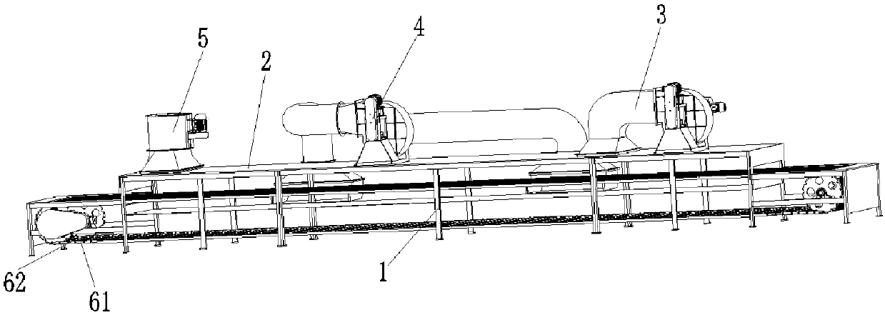
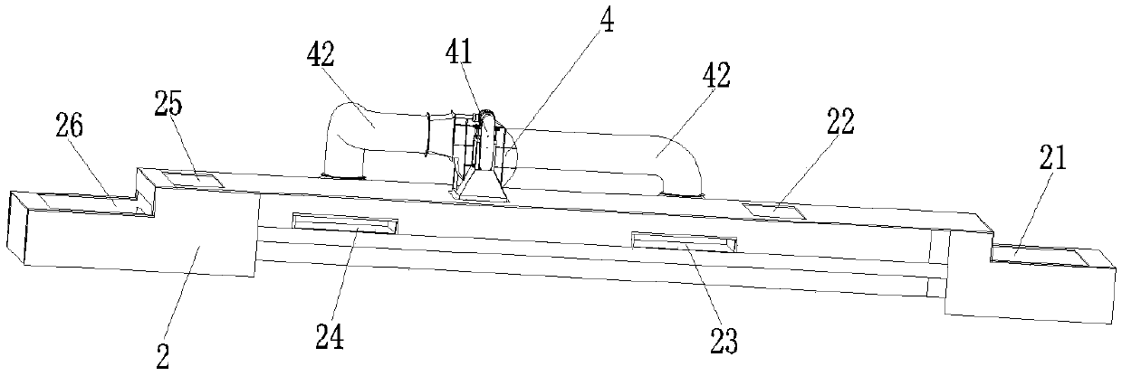
[0024] A kind of ceramic drying equipment provided by the present invention, such as Figure 1 to Figure 3 As shown, it includes a frame 1, a drying box 2, an air inlet device 3, an air circulation device 4, an air outlet device 5 and a conveyor belt 6; the drying box 2 is surrounded by a top plate, a side plate and a bottom plate; Installed on the frame 1 , the conveyor belt 6 passes through the drying box 2 and is used to transport the ceramic products 7 from the feed port 21 of the drying box 2 to the discharge port 26 . The top plate of drying box 2 is provided with air inlet 22 and air...


PUM


Abstract

The invention relates to the field of ceramic manufacturing equipment, in particular to ceramic drying equipment. According to the ceramic drying equipment, an air circulating device is additionally arranged on a drying box; and the horizontal height of a first circulating air opening and the horizontal height of a second circulating air opening are arranged to be smaller than that of a conveyingbelt in the drying box. In this way, in the drying process, the air circulating device can rapidly convey low-temperature air gathered at the bottom of the drying box from the first circulating air opening to the second circulating air opening, and in other words, the low-temperature air is conveyed to the end, provided with an air outlet, of the drying box, so that air flowing inside the drying box is increased; meanwhile, the air flows from the second circulating air opening which is small in horizontal height to the air outlet which is large in horizontal height in the place close to the air outlet, and the bottom part of a ceramic product can also be dried; and the drying effect is improved.

Description

technical field [0001] The invention relates to the field of ceramic manufacturing equipment, in particular to a ceramic drying equipment. Background technique [0002] Ceramics are various products made from natural clay and various natural minerals through crushing, kneading, molding and calcination. The drying of ceramics is one of the very important processes in the production process of ceramics. Most of the quality defects of ceramic products are caused by improper drying. [0003] Existing ceramic drying equipment generally includes a drying box, and the ceramics in the drying box are dried by sending dry hot air into the drying box. The existing ceramic drying equipment has the following problems: after the hot air is transported into the drying box and contacts the ceramic products, the hot air will be cooled down to lower temperature air, and the cooled air will gather in the drying box. At the bottom, the accumulated lower temperature air will affect the circula...

Claims


Application Information

Patent Timeline
IPC IPC(8): F26B15/04F26B21/02F26B21/06F26B21/10
CPCF26B15/04F26B21/001F26B21/02F26B21/06F26B21/10F26B2210/02
Inventor 高秋红
Owner FOSHAN WANSHAN ENVIRONMENTAL PROTECTION TECH CO LTD
Why Eureka
Try Eureka