Antenna area array thermal deformation non-contact measurement system under thermal vacuum environment

A non-contact measurement, thermal vacuum technology, applied in the field of measurement systems, to achieve the effect of solving occlusion problems, high precision, and high degree of automation

Inactive Publication Date: 2018-04-20
SHANGHAI INST OF SATELLITE EQUIP
View PDF5 Cites 10 Cited by
  • Summary
  • Abstract
  • Description
  • Claims
  • Application Information

AI Technical Summary

Problems solved by technology

In the current test method, digital photogrammetry based on stereo vision is usually used to measure the thermal deformation of the antenna array. However, when the measurement camera is introduced into the vacuum tank, key technologies such as protection, movement, and measurement accuracy must be solved.

Method used


Image

  • Antenna area array thermal deformation non-contact measurement system under thermal vacuum environment

Examples


Embodiment Construction

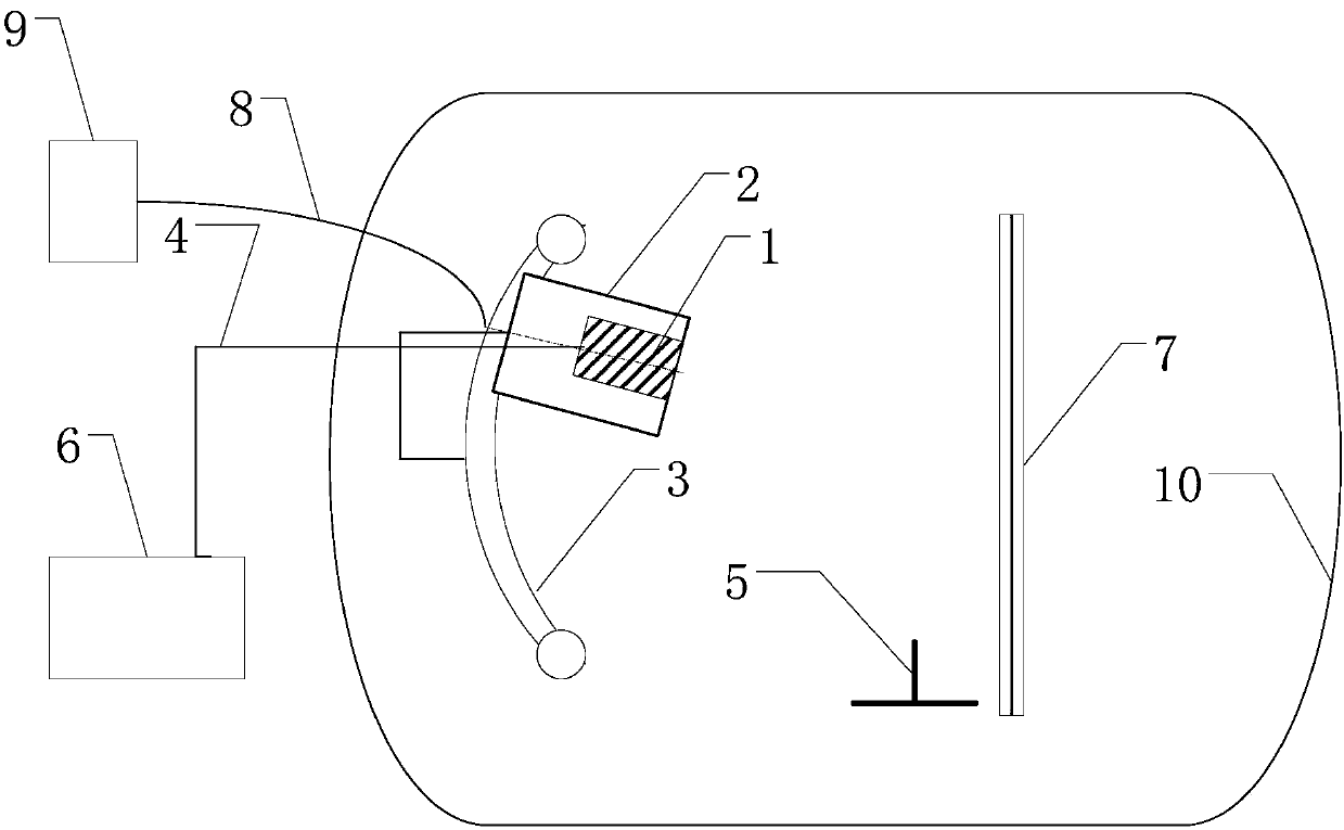
[0016] The following will combine figure 1 A further detailed description is made on the thermal deformation non-contact measurement system of an antenna array in a thermal vacuum environment of the present invention.

[0017] Such as figure 1 As shown, the embodiment of the present invention provides a non-contact measurement system for antenna array thermal deformation in a thermal vacuum environment. Under the protection of the protection device of the measuring camera in a thermal vacuum environment, the system passes the measuring camera two in a thermal vacuum environment. The three-dimensional movement device completes the two-dimensional movement, and realizes the image acquisition of the object to be measured at different positions. At the same time, the zero-expansion glass-ceramic standard ruler fixed in the vacuum cryogenic container provides the length reference, and the image is processed by the thermal deformation measurement control and analysis software. calc...


PUM


Abstract

The invention discloses an antenna area array thermal deformation non-contact measurement system under a thermal vacuum environment. The system comprises a control terminal internally equipped with thermal deformation measurement control and analysis software, a measuring camera and a protection device for the measuring camera under the thermal vacuum environment. The control terminal is arrangedoutside a vacuum tank, and is connected with the measuring camera arranged in the vacuum tank through a motion control and data collection cable; the measuring camera is arranged in the protection device for the measuring camera under the thermal vacuum environment through a fixture; and the vacuum tank is also equipped with a measuring camera two-dimensional motion device, an antenna area array and a zero-expansion microcrystalline glass reference scale. The system can realize thermal deformation measurement of the antenna area array under the thermal vacuum environment by enabling one measuring camera to finish two-dimensional motion in the thermal vacuum environment and carry out image acquisition on an object to be measured at different positions, and carrying out calculation through the corresponding measurement control and analysis software; and the system has the advantages of non-contact, high precision and high degree of automation.

Description

technical field [0001] The invention relates to a measurement system, in particular to a non-contact measurement system for thermal deformation of an antenna array in a thermal vacuum environment. Background technique [0002] At present, with the continuous development of satellite high-precision and high-resolution indicators, the requirements for the shape of the antenna array are getting higher and higher in the satellite development process, and the antenna array will be subject to alternating cold and heat and temperature in the space vacuum and low temperature environment. The thermal deformation of the surface caused by the gradient effect must solve the problem of measuring the thermal deformation of the antenna array during the vacuum thermal test. In the current test method, digital photogrammetry based on stereo vision is usually used to measure the thermal deformation of the antenna array, but when the measurement camera is introduced into the vacuum tank, key t...

Claims


Application Information

Patent Timeline
Patent Type & Authority Applications(China)
IPC IPC(8): G01B11/16
CPCG01B11/16
Inventor 李钰艾卓张世一王根源刘瑞芳孙永雪
Owner SHANGHAI INST OF SATELLITE EQUIP
Why Eureka
Try Eureka