
Distributed fiber strain coefficient calibration device and method

An optical fiber strain and calibration device technology, applied in the direction of using optical devices, measuring devices, instruments, etc., can solve the problems of optical fiber strain coefficient calibration errors, small, unsuitable optical fibers, etc. Effect

Active Publication Date: 2018-04-20
CHINA UNIV OF GEOSCIENCES (WUHAN)
View PDF6 Cites 8 Cited by
  • Summary
  • Abstract
  • Description
  • Claims
  • Application Information

AI Technical Summary

Problems solved by technology

Therefore, in the traditional measurement method, at the junction of the tensioned section and the untensioned section of the optical fiber, the measurement results often change gradually, rather than drastically. The deep frequency shift value is too small, which will cause errors in the calibration of the optical fiber gauge factor
In addition, the traditional method stretches the optical fiber at a fixed point, and fixes the optical fiber by clamping or pasting thin aluminum sheets. This is suitable for bare optical fibers or optical fibers with low tensile strength, but for armored optical fibers and other optical fibers reinforced with steel wires Not applicable

Method used


Image

  • Distributed fiber strain coefficient calibration device and method
  • Distributed fiber strain coefficient calibration device and method

Examples


Embodiment Construction

[0024] In order to make the purpose, technical solution and advantages of the present invention clearer, the embodiments of the present invention will be further described below in conjunction with the accompanying drawings.

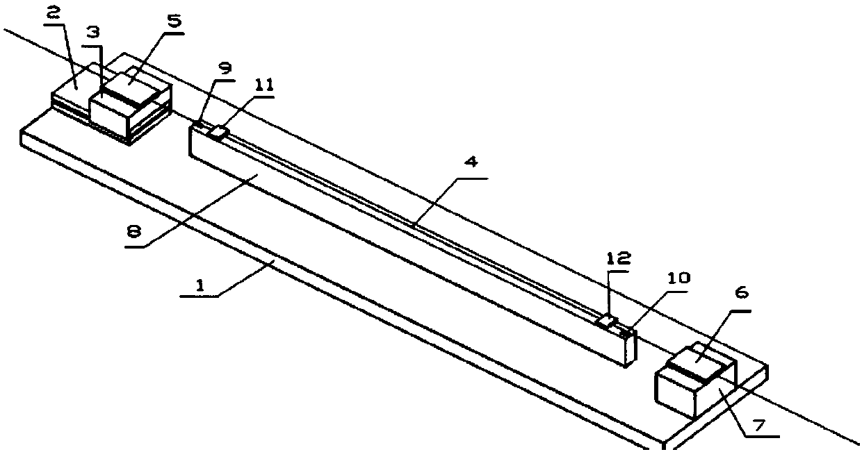
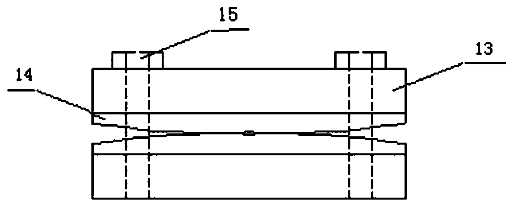
[0025] Please refer to figure 1 , the embodiment of the present invention provides a fully distributed optical fiber gauge coefficient calibration device, including a test bench 1, a hydraulic stretching mechanism and an optical fiber clamp, and the hydraulic stretching mechanism includes a lower sliding table 2 and an upper sliding block 3 , the slide table 2 is fixed on the experimental bench 1, the optical fiber clamp includes a first clamp 5 and a second clamp 6 oppositely arranged for clamping the optical fiber 4, and the first clamp includes the same two metal Block 13 and the same two rubber pads 14, the two metal blocks 13 clamp the two rubber pads 14 that fit together, after the optical fiber 4 passes between the two rubber pads 14, the two meta...


PUM


Abstract

The invention provides a distributed fiber strain coefficient calibration device, and the device comprises an experiment table, a hydraulic stretching mechanism and a fiber clamping tool. The hydraulic stretching mechanism comprises a sliding table and a sliding block, and the sliding table is fixed on the experiment table. The fiber clamping tool comprises a first clamping tool and a second clamping tool, wherein the first clamping tool is fixed on the sliding block, and the second sliding tool is fixed on the experiment table. The device also comprises a displacement measurement mechanism, and the displacement measurement mechanism comprises a sliding rail, a first displacement meter, a second displacement meter, a first passive sliding block, and a second passive sliding block. The sliding rail is fixed on the experiment table, and two ends of the sliding rail are respectively provided with the first displacement meter and a second displacement meter in a fixed manner. The sliding rail is provided with the first passive sliding block and a second passive sliding block. When the sliding block pulls a fiber to make movement along the sliding table, the first and second passive sliding blocks make synchronous movement with a fiber. The beneficial effects of the invention are that the device solves problems that the fiber deformation measurement is not accurate and the spatial resolution affects the Brillouin frequency shift value, and the device improves the measurement accuracy of a strain coefficient.

Description

technical field [0001] The invention relates to the technical field of fully distributed optical fiber sensing, in particular to a fully distributed optical fiber gauge factor calibration device and method. Background technique [0002] The basic principle of fully distributed optical fiber sensing technology is that when the optical fiber is affected by environmental factors such as external stress and temperature, the characteristic parameters of the light wave transmitted in the optical fiber, such as phase, frequency, polarization state, etc., will change accordingly. By detecting the changes of these parameters , the information of the external measured parameters can be obtained. At present, the fully distributed optical fiber sensing technology based on Brillouin scattering mainly includes Brillouin Optical Time Domain Reflectometry (BOTDR) technology, Brillouin Optical Time Domain Analysis (BOTDA) technology, and Brillouin Optical Frequency Domain Analysis (BOFDA) te...

Claims


Application Information

Patent Timeline
IPC IPC(8): G01B11/16
CPCG01B11/16
Inventor 安鹏举邓清禄唐辉明蒋孝鹏韦超群申培武宁奕冰何成
Owner CHINA UNIV OF GEOSCIENCES (WUHAN)
Learn More