Control method, main control device and zero-crossing detection circuit
A technology of zero-crossing detection and main control equipment, which is applied to the program control, measurement of electrical variables, and electrical program control in the sequence/logic controller, which can solve the problems of missed judgment, inability to complete discharge, and misjudgment, etc., and achieve reduction The risk of misjudgment and the effect of improving accuracy
- Summary
- Abstract
- Description
- Claims
- Application Information
AI Technical Summary
Problems solved by technology
Method used
Image


Examples
Embodiment 1
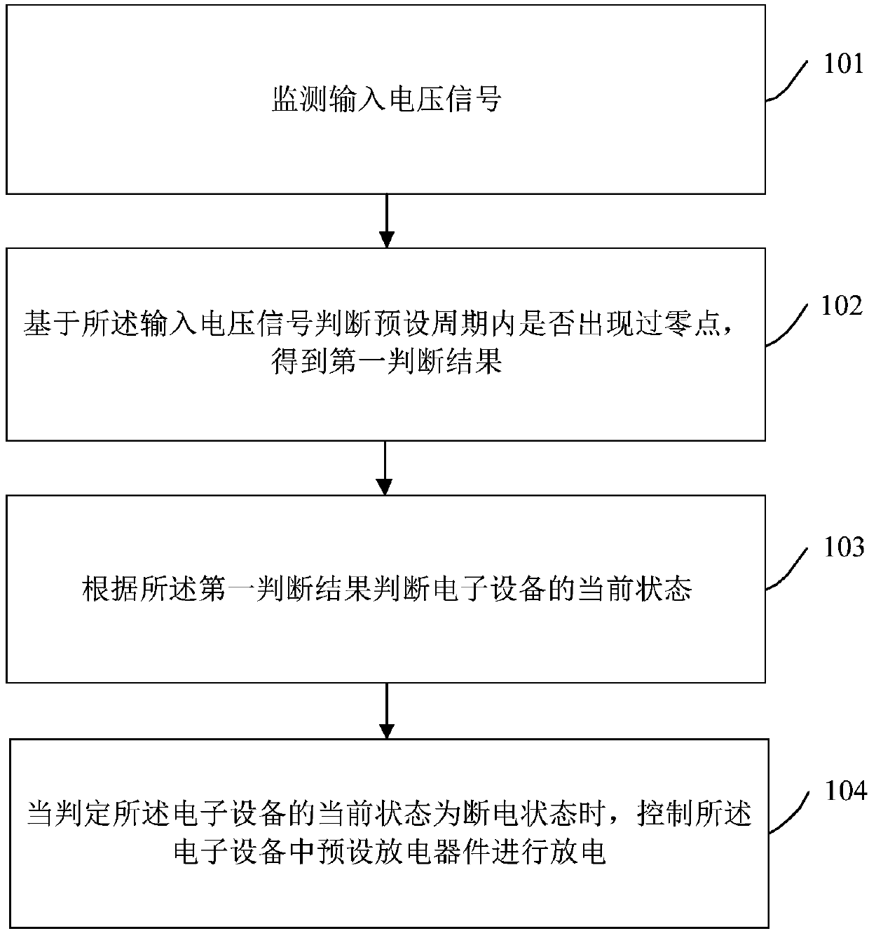
[0081] figure 1 It is a schematic diagram of the implementation flow of a control method provided by the embodiment of the present invention. The control method in this example is applied to electronic equipment, such as figure 1 As shown, the control method mainly includes the following steps:
[0082] Step 101: Monitor the input voltage signal.
[0083] Here, the input voltage signal can be monitored by the main control device of the electronic device. Wherein, the input voltage signal refers to a signal input to the main control device.
[0084] In an embodiment, the manner of obtaining the input voltage signal includes:
[0085] The rectification device of the electronic device performs full-wave rectification on the incoming AC signal, and rectifies the AC signal into a first electrical signal; wherein, the period of the first electrical signal is the period of the AC signal Half, the waveform corresponding to the first electrical signal is continuous and composed of ...
Embodiment 2
[0144] Figure 4 A schematic diagram of the implementation flow of the main control device controlling the discharge of the preset discharge device provided by the embodiment of the present invention, as shown in Figure 4 As shown, the process includes:
[0145] Step 401: the main control device monitors the input voltage signal;
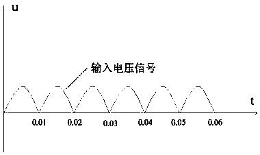
[0146] Here, the form of the waveform corresponding to the input voltage signal is not limited. For example, the waveform corresponding to the input voltage signal may be the first input voltage waveform diagram as shown in FIG. 2( e ). The waveform corresponding to the input voltage signal may be a second input voltage waveform diagram as shown in FIG. 2( d ).
[0147] Step 402: The main control device judges whether a zero-crossing point occurs within a preset period based on the input voltage signal, and if a zero-crossing point occurs, execute step 403; if no zero-crossing point occurs, execute step 405;
[0148] Step 403: The master control...
Embodiment 3
[0160] An embodiment of the present invention provides a master control device, Figure 5 A schematic diagram of the composition and structure of the main control device provided by the embodiment of the present invention, such as Figure 5 As shown, the main control device includes: a monitoring unit 51, a first judging unit 52, a second judging unit 53, and a control unit 54; wherein,
[0161] The monitoring unit 51 is configured to monitor an input voltage signal;
[0162] The first judging unit 52 is configured to judge whether a zero-crossing point occurs within a preset period based on the input voltage signal, and obtain a first judging result;
[0163] The second judging unit 53 is configured to judge the current state of the electronic device according to the first judging result;
[0164] The control unit 54 is configured to control the preset discharge device in the electronic device to discharge when it is determined that the current state of the electronic devic...
PUM
 Abstract
Description
Claims
Application Information
 - R&D
- Intellectual Property
- Life Sciences
- Materials
- Tech Scout
- Unparalleled Data Quality
- Higher Quality Content
- 60% Fewer Hallucinations
Browse by: Latest US Patents, China's latest patents, Technical Efficacy Thesaurus, Application Domain, Technology Topic, Popular Technical Reports.
© 2025 PatSnap. All rights reserved.Legal|Privacy policy|Modern Slavery Act Transparency Statement|Sitemap|About US| Contact US: help@patsnap.com