
Battery cell grabbing structure

A technology of grasping structure and cell, applied in circuits, electrical components, primary batteries, etc., can solve problems such as poor blanking, long procurement cycle, cell shaking, etc., to achieve the effect of convenient processing

Pending Publication Date: 2018-04-20
ZHENJIANG CINNIC AUTOMATIC TECH CO LTD
View PDF6 Cites 7 Cited by
  • Summary
  • Abstract
  • Description
  • Claims
  • Application Information

AI Technical Summary

Problems solved by technology

[0002] In the automatic lithium battery production and assembly line, how to automatically grab the battery cell must be considered. At present, the grabbing structure used to grab the battery cell is realized by clamping (releasing) through the movement of the air claw, but The price of the air claw is relatively expensive, the purchase cycle is relatively long, and there is a large gap between the guide rod protruding from the gripper and the gripper. When the battery is grabbed, the battery will shake. , the guide rod of the air claw is bent, and the reference of the air claw is positioned at the center, which will cause poor blanking and add trouble to the next process

Method used


Image

  • Battery cell grabbing structure
  • Battery cell grabbing structure

Examples


Embodiment approach 1

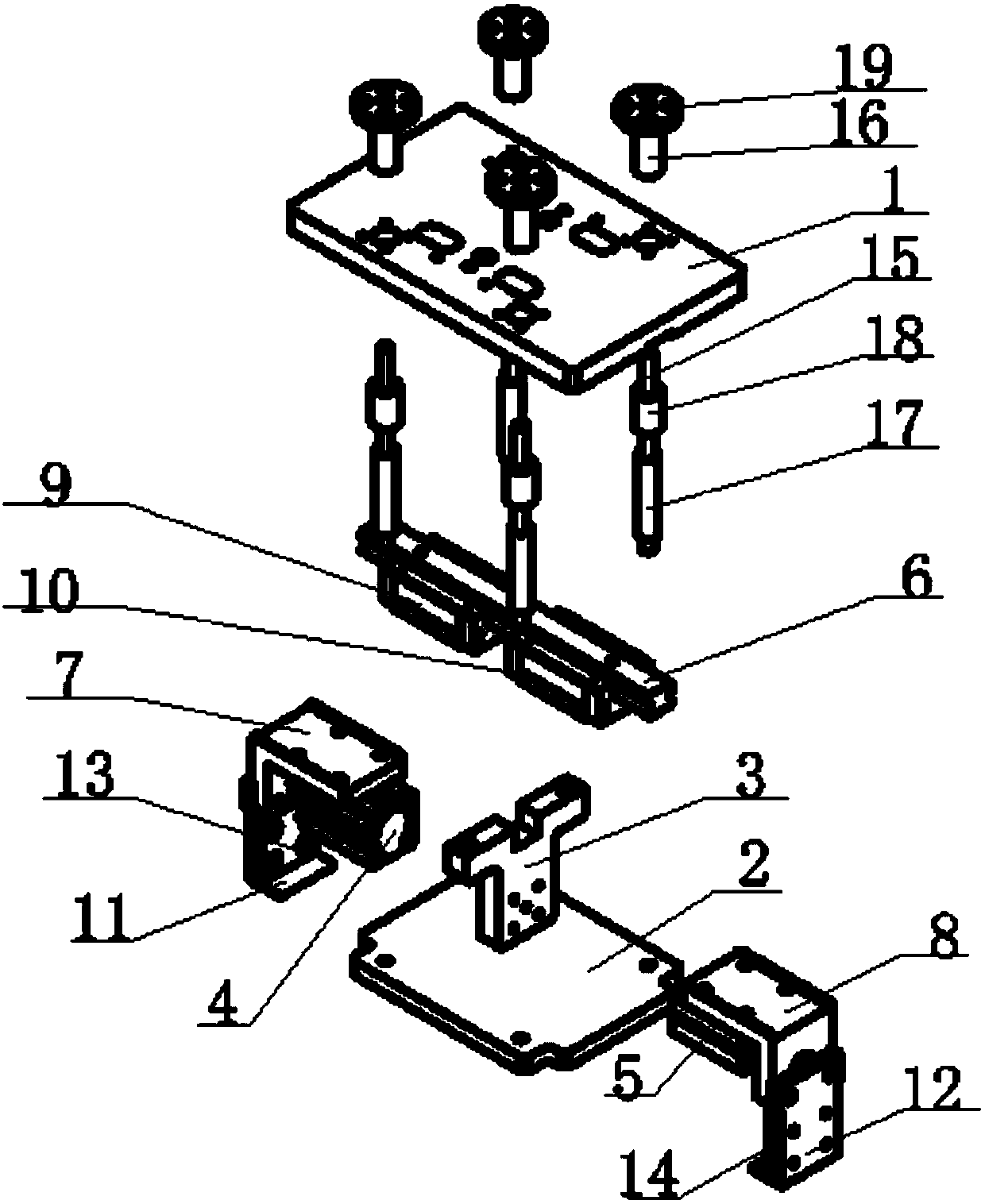
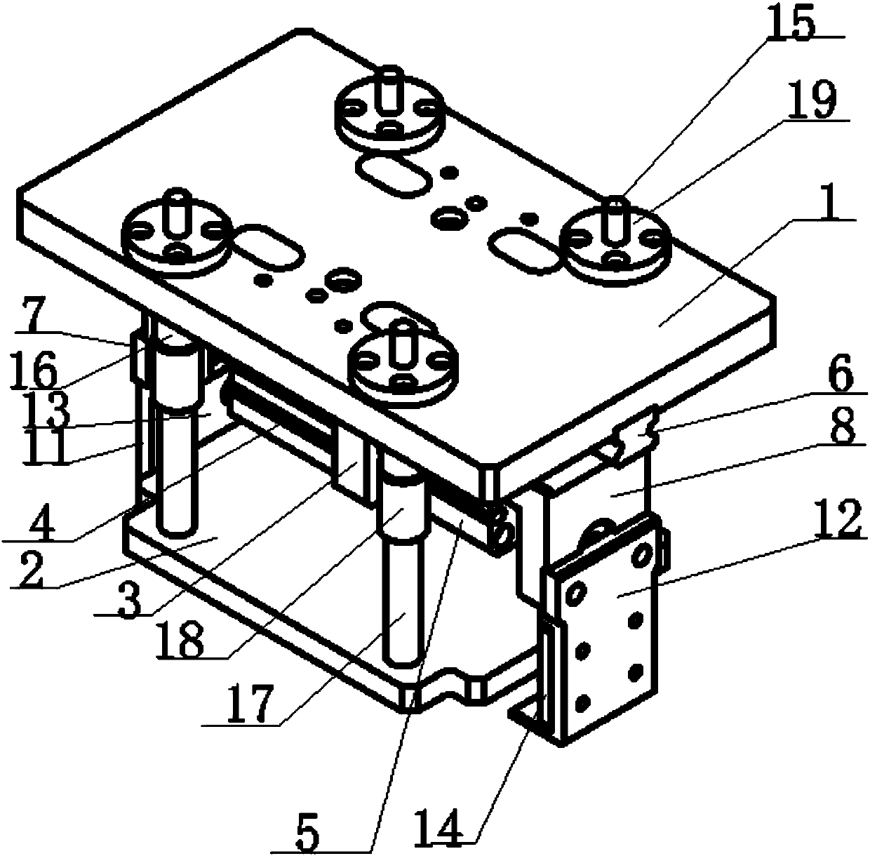
[0016] This embodiment provides a cell grasping structure, such as figure 1 and 2 As shown, it mainly consists of top plate 1, pressure plate 2, cylinder fixing plate 3, first cylinder 4, second cylinder 5, horizontal guide rail 6, first slider mounting plate 7, second slider mounting plate 8, first slider 9. The second slider 10, the left jaw 11, the right jaw 12, the first insulating plate 13, the second insulating plate 14, four guide shafts 15, four linear bearings 16, four springs 17, four spacers Cover 18 and four fixing rings 19 are formed.

[0017] Wherein, the first insulating plate 13 is installed on the inner side of the left jaw 11, the second insulating plate 14 is installed on the inner side of the right jaw 12, the left jaw 11 is installed on the bottom of the first slider mounting plate 7, and the right jaw 12 Installed on the bottom of the second slider mounting plate 8.

[0018] The fixed ends of the first cylinder 4 and the second cylinder 5 with differen...


PUM


Abstract

The invention relates to the technical field of lithium batteries, and discloses a battery cell grabbing structure. A bottom surface of a horizontal guide rail is fixed on the lower surface of a top board, upper parts of a first slide block and a second slide block are slidably connected with the horizontal guide rail, lower parts of the first slide block and the second slide block are respectively fixed on top surfaces of a first slide block installation board and a second slide block installation board, a left claw and a right claw are respectively fixed at lower parts of the first slide block installation board and the second slide block installation board, fixed ends of a first air cylinder and a second air cylinder are respectively fixed at two sides of an air cylinder fixing board, telescopic ends of the first air cylinder and the second air cylinder are respectively fixedly connected with the first slide block installation board and the second slide block installation board, theair cylinder fixing board is fixed at the bottom of the top board, and the cylinder diameters of the first air cylinder and the second air cylinder are different. When the battery cell grabbing structure is used for grabbing a battery cell, the reference of the structure is maintained, a processed piece replaces an air claw, the claw is less likely to be cracked up, and the battery cell does notswing when being grabbed.

Description

technical field [0001] The invention relates to the technical field of lithium batteries, in particular to a cell grasping structure. Background technique [0002] In the automatic lithium battery production and assembly line, how to automatically grab the battery cell must be considered. At present, the grabbing structure used to grab the battery cell is realized by clamping (releasing) through the movement of the air claw, but The price of the air claw is relatively expensive, the purchase cycle is relatively long, and there is a large gap between the guide rod protruding from the gripper and the gripper. When the battery is grabbed, the battery will shake. , The guide rod of the air claw is bent, and the reference of the air claw is positioned at the center, which will cause poor blanking and increase troubles for the next process. Contents of the invention [0003] Purpose of the invention: Aiming at the problems existing in the prior art, the present invention provid...

Claims


Application Information

Patent Timeline
Patent Type & Authority Applications(China)
IPC IPC(8): H01M10/04H01M6/00
CPCH01M6/005H01M10/0404Y02P70/50
Inventor 袁伟宏吉跃华
Owner ZHENJIANG CINNIC AUTOMATIC TECH CO LTD
Learn More