Heat dissipation structure of motor stator
A heat dissipation structure, motor stator technology, applied in the direction of the shape/style/structure of the magnetic circuit, the shape/style/structure of the winding conductor, the shape/style/structure of the winding insulation, etc., can solve the problem that it is difficult to ensure the heat dissipation performance of the motor , to achieve the effect of increasing ventilation and cooling efficiency, improving heat dissipation efficiency, and avoiding electromagnetic damage
- Summary
- Abstract
- Description
- Claims
- Application Information
AI Technical Summary
Problems solved by technology
Method used
Image
Examples
Embodiment 1
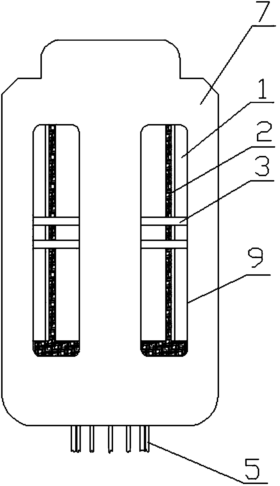
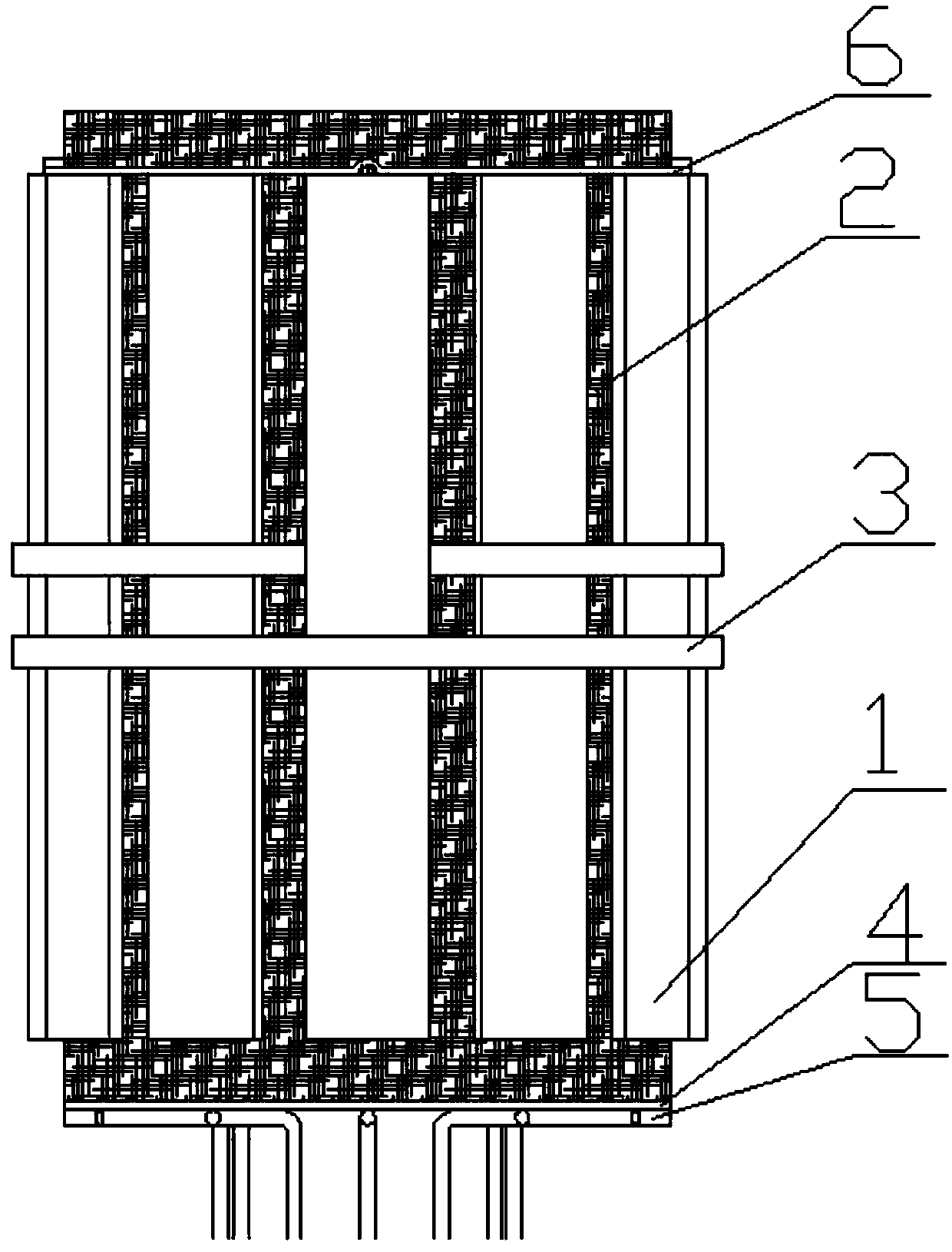
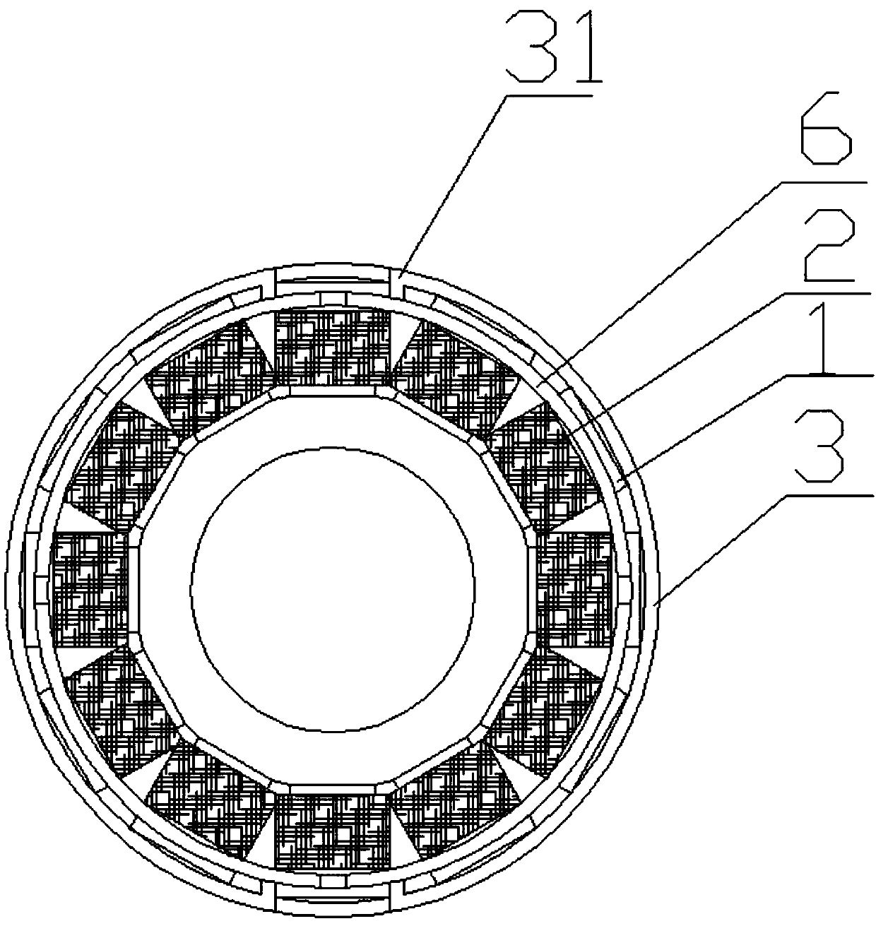
[0036] figure 1 It is the front view of the present invention, figure 2 It is the front view of the stator structure of the present invention, image 3 It is a top view of the stator structure of the present invention, Figure 4 It is a bottom view of the stator structure of the present invention, Figure 5 It is a partially enlarged view of the lead wire bayonet part of Embodiment 1 of the present invention. As shown in the figure, a motor stator heat dissipation structure includes a motor casing 7, a stator core 1, a stator coil 2, an insulating and heat-conducting layer 4, and a heat-conducting wire 5; The bottom of the stator coil 2 is provided with an insulating and heat-conducting layer 4, which is closely attached to the stator coil 2. The other side of the insulating and heat-conducting layer 4 is provided with several heat-conducting wires 5; the top of the stator core 1 is provided with a lead wire pressing plate 6, It is closely attached to the stator core 1, th...
Embodiment 2
[0043] Such as Figure 1-Figure 4 A motor stator heat dissipation structure is shown, including a motor casing 7, a stator core 1, a stator coil 2, an insulating and heat-conducting layer 4, and a heat-conducting wire 5; The other side of the insulating and heat-conducting layer 4 is provided with 12 heat-conducting wires 5; the top of the stator core 1 is provided with a lead pressing plate 6, which is closely attached to the stator core 1, and the lead pressing plate 6 is ring-shaped, so The lead wire pressing plate 6 is provided with 4 lead wire bayonets 8, and the outside of the stator core 1 is provided with two sets of stator pressing pieces 3, and any one set of stator pressing pieces 3 is fixed inside the motor housing 7, and any one of the stator pressing pieces 3 A group of stator pressing pieces 3 are two symmetrical semicircular rings, there is a gap opening between the two semicircular rings of any one set of stator pressing pieces 3, and the two groups of stator ...
Embodiment 3
[0053] Three permanent magnet brushless DC motors need to be used in the same equipment at the same time, and the three motors all use Figure 1-Figure 4 A motor stator heat dissipation structure is shown, including a motor casing 7, a stator core 1, a stator coil 2, an insulating and heat-conducting layer 4, and a heat-conducting wire 5; The other side of the insulating and heat-conducting layer 4 is provided with 8 heat-conducting wires 5; the top of the stator core 1 is provided with a lead pressing plate 6, which is closely attached to the stator core 1, and the lead pressing plate 6 is ring-shaped, so The lead wire pressing plate 6 is provided with three lead wire bayonets 8, and the outside of the stator core 1 is provided with two sets of stator pressing pieces 3, and any one set of stator pressing pieces 3 is fixed inside the motor housing 7, and any one of the stator pressing pieces 3 A group of stator pressing pieces 3 are two symmetrical semicircular rings, there is...
PUM
 Abstract
Description
Claims
Application Information
 - R&D
- Intellectual Property
- Life Sciences
- Materials
- Tech Scout
- Unparalleled Data Quality
- Higher Quality Content
- 60% Fewer Hallucinations
Browse by: Latest US Patents, China's latest patents, Technical Efficacy Thesaurus, Application Domain, Technology Topic, Popular Technical Reports.
© 2025 PatSnap. All rights reserved.Legal|Privacy policy|Modern Slavery Act Transparency Statement|Sitemap|About US| Contact US: help@patsnap.com


