Cleaning machine

A cleaning machine and motor assembly technology, applied in the field of cleaning machines, can solve the problems affecting the heat dissipation effect of the motor, affecting the performance and service life of the cleaning machine, etc., and achieve the effect of avoiding mutual interference of heat dissipation and improving performance and service life.

Pending Publication Date: 2018-04-20
CHANGZHOU GLOBE
1 Cites 1 Cited by

AI-Extracted Technical Summary

Problems solved by technology

However, this heat dissipation method will affect the heat dissipation effect of th...

Method used

In summary, cleaning machine 100 of the present invention is owing to be provided with the dual cooling air channel that does not interfere with each other, thereby avoids the problem that described motor 21 heat dissipation and high-power controller 31 heat dissipation interfere with each other, and then improves described motor 21. The heat dissipation effect of the high-power controller 31 improves the performance and service life of the cleaning machine 100 .
[0026] The heat sink 32 protrudes toward the fan 33 to form a plurality of cooling ribs 321, so as to increase the heat dissipation area of ​​the heat sink 32, thereby improving heat dissipation efficiency. The fan 33 is installed on the heat dissipation ribs 321 , so that wind enters the fan 33 from the gap of the heat dissipation ribs 321 , so as to dissipate heat from the heat dissipation fins 32 . The isolation plate 34 isolates the heat sink 32 from the fan 33, so as to prevent the wind from the fan 33 from flowing back to the heat sink 32 or control the air from the gap between the fan 33...

Abstract

The invention provides a cleaning machine, which includes a high-pressure pump, a motor assembly, a control assembly, and a housing; the motor assembly includes a motor that drives the high-pressure pump to run, a fan blade installed on the motor, and a housing that accommodates the motor. The wind cover; the housing is provided with a first storage cavity for storing the motor assembly, a second storage cavity for storing the control assembly, and a partition separating the first storage cavity and the second storage cavity; the The casing is also provided with an air inlet part and an air outlet part; the air inlet part, the first storage chamber, the wind cover and the air outlet part form a first air passage; the air inlet part, the second storage chamber, and the air outlet part Form the second air duct. Compared with the prior art, the cleaning machine of the present invention has dual heat dissipation air ducts that do not interfere with each other, thereby avoiding the mutual interference between the heat dissipation of the motor and the heat dissipation of the high-power controller, thereby improving the heat dissipation effect of the motor and the high-power controller , improving the performance and service life of the cleaning machine.

Application Domain

Cooling/ventillation arrangementSupports/enclosures/casings

Technology Topic

Power controlEngineering +5

Image

  • Cleaning machine
  • Cleaning machine
  • Cleaning machine

Examples

  • Experimental program(1)

Example Embodiment

[0021] In order to make the objectives, technical solutions and advantages of the present invention clearer, the present invention will be described in detail below with reference to the accompanying drawings and specific embodiments.
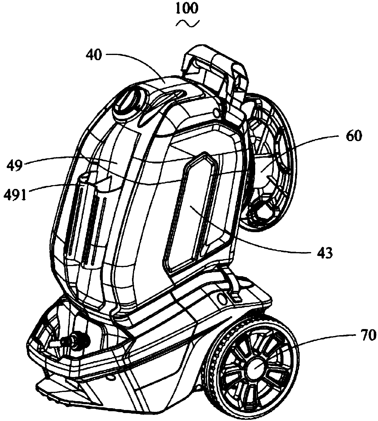
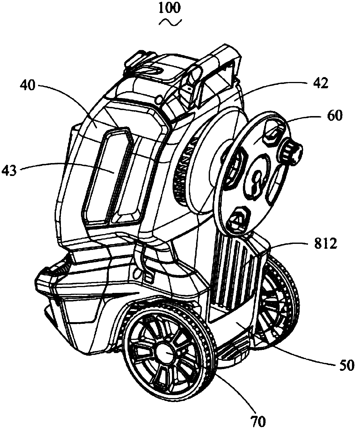
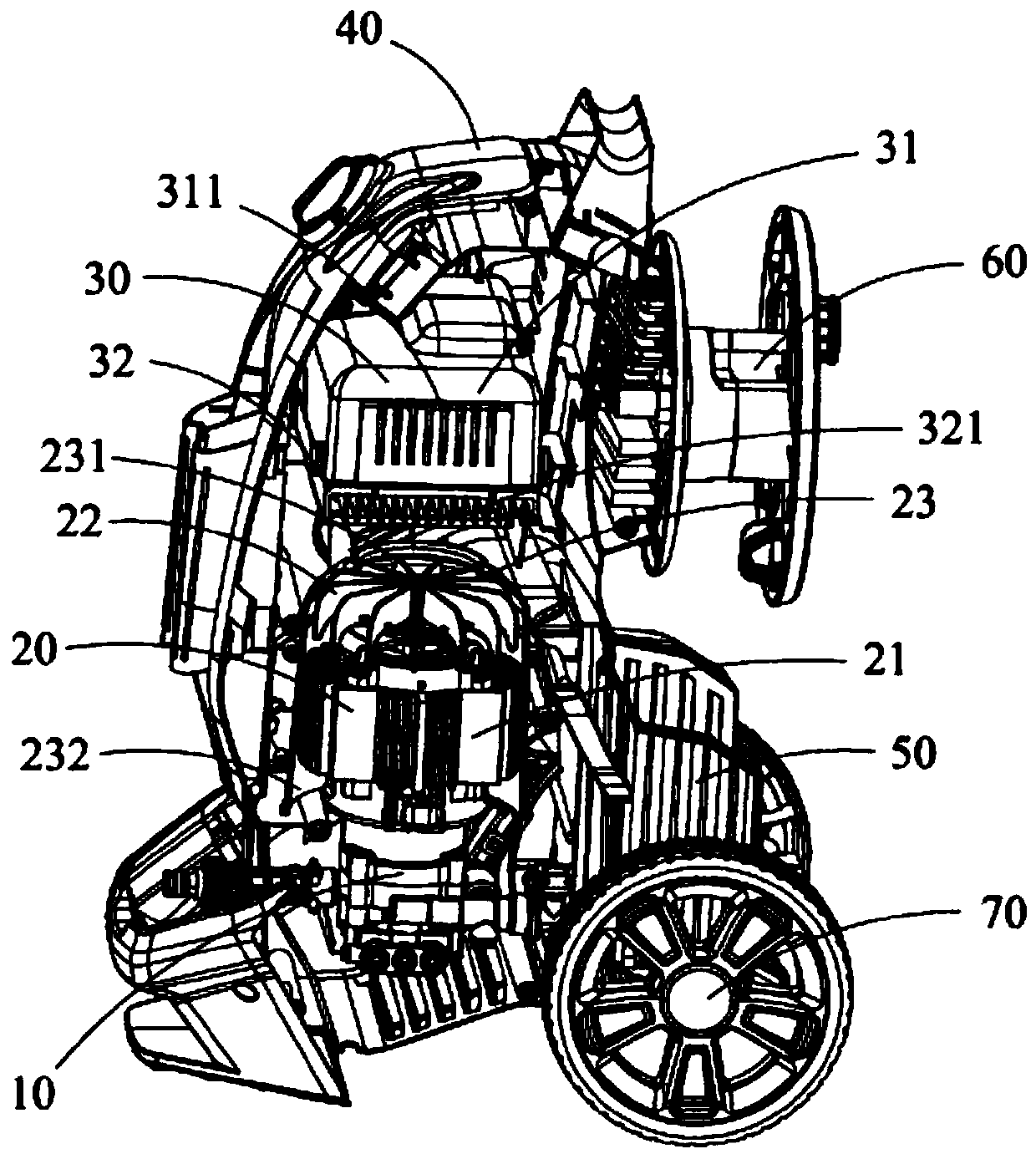
[0022] See figure 1 , figure 2 as well as image 3 As shown, the cleaning machine 100 of the present invention includes a high-pressure pump 10, a motor assembly 20 matched with the high-pressure pump 10, a control assembly 30 that controls the motor assembly 20, and houses the high-pressure pump 10, the motor assembly 20, and the The housing 40 of the control assembly 30, the accessory pocket 50, the hose reel 60 and the roller 70 installed on the housing 40.
[0023] See image 3 As shown, the high-pressure pump 10 is used to pressurize the liquid flowing through the high-pressure pump 10. The motor assembly 20 includes a motor 21 that drives the high-pressure pump 10 to operate, a fan blade 22 installed at the rear of the motor 21 and a wind cover 23 that houses the motor 21. The wind shield 23 has an air inlet 231 close to the fan blade 22 and an air outlet 232 far away from the fan blade 22. The motor 21 is located between the air inlet 231 and the air outlet 232.
[0024] See image 3 as well as Figure 4 As shown, the control assembly 30 includes a high-power controller 31 that controls the operation of the motor 21, a heat sink 32 mounted on the controller 31, a fan 33 mounted on the heat sink 32, and a fan 33 mounted on the heat sink 32. The isolation plate 34 between the heat sink 32 and the fan 33. In the present invention, the isolation plate 34 is a plate-like structure extending inward from the housing 40 to separate the heat sink 32 and the fan 33 to prevent wind from exiting the fan 33 It flows back from the gap between the fan 33 and the casing 40 to the heat sink 32 or the controller 31. Of course, in other embodiments, the isolation plate 34 can also be provided separately from the housing 40, that is, the isolation plate 34 can effectively prevent the wind from the fan 33 from flowing back. .
[0025] The casing of the controller 31 is provided with a vent 311 to facilitate cooling air from the vent 311 into the casing of the controller 31 to cool and dissipate the circuit board. The heat sink 32 is an aluminum cooling plate, which is installed at the bottom of the controller 31 to cool and dissipate the controller 31.
[0026] The heat sink 32 is formed with a plurality of heat dissipation ribs 321 protruding toward the fan 33 to increase the heat dissipation area of ​​the heat sink 32, thereby improving the heat dissipation efficiency. The fan 33 is installed on the radiating ribs 321 so that wind enters the fan 33 from the gaps of the radiating ribs 321 to realize the heat dissipation of the heat sink 32. The isolation plate 34 isolates the heat sink 32 from the fan 33 to prevent the wind from the fan 33 from flowing back to the heat sink 32 from the gap between the fan 33 and the housing 40 or to control In this way, the heat dissipation effect of the controller 31 is affected.
[0027] See figure 1 , figure 2 as well as Figure 5 As shown, the housing 40 includes a front wall 41, a rear wall 42 opposite to the front wall 41, a pair of side walls 43, a bottom wall 44 and a partition 45. The front wall 41, the rear wall 42, the side walls 43, and the bottom wall 44 jointly enclose a receiving space, and the partition 45 divides the receiving space into the first part of the high-pressure pump 10 and the motor assembly 20. The receiving cavity 46 and the second receiving cavity 47 for receiving the control assembly 30. The housing 40 is further provided with an accessory receiving cavity 48 for receiving the accessory pocket 50, and the accessory receiving cavity 48 is communicated with the first receiving cavity 46.
[0028] See Figure 5 As shown, the housing 40 is also provided with an air inlet 81 and an air outlet 82. The air inlet 81, the first accommodating cavity 46, the wind hood 23, and the air outlet 82 jointly constitute a first air duct, and the air inlet 81, the second accommodating cavity 47, and the air outlet 82 jointly constitute a second air duct. Tao.
[0029] The air inlet 81 includes a first air inlet louver 811 arranged on the rear wall 42 and a second air inlet louver 812 arranged on the accessory pocket 50. The air outlet portion 82 includes a first air outlet louver 821 arranged on the front wall 41 and a second air outlet louver 822 arranged on the bottom wall 44. The hose reel 60 is installed on the rear wall 42 and is opposite to the first air inlet louver 811. The housing 40 is also provided with a front panel 49 installed on the front wall 41, and a gun hanger 491 and a third wind shutter that cooperate with the first wind shutter 821 are arranged on the front panel 49. (Not shown).
[0030] When the washing machine 100 is running, the fan blade 22 is driven by the motor 21 to rotate, so that the cold air outside the housing 40 runs along the first air duct from the air inlet 81 To the air outlet 82, the motor 21 is further cooled and dissipated. The fan 33 drives the cold air outside the housing 40 to run along the air inlet portion 81 along the second air duct to the air outlet portion 82, so as to realize cooling and heat dissipation of the controller 31. Since the partition 45 is provided, the hot air blown by the fan 33 after cooling the controller 31 and the heat sink 32 cannot enter the first accommodating cavity 46, which can effectively prevent the motor 21 from dissipating heat and causing damage. The heat dissipation of the controller 31 interferes with each other, thereby improving the heat dissipation effect of the motor 21 and the controller 31, and improving the performance and service life of the cleaning machine 100.
[0031] In summary, the cleaning machine 100 of the present invention is provided with dual heat dissipation air ducts that do not interfere with each other, thereby avoiding the problem of mutual interference between the heat dissipation of the motor 21 and the heat dissipation of the high-power controller 31, thereby improving the motor 21, The heat dissipation effect of the power controller 31 improves the performance and service life of the cleaning machine 100.
[0032] The above embodiments are only used to illustrate the technical solutions of the present invention and not to limit them. Although the present invention has been described in detail with reference to the preferred embodiments, those of ordinary skill in the art should understand that the technical solutions of the present invention can be modified or equivalently replaced. Without departing from the spirit and scope of the technical solution of the present invention.

PUM

no PUM

Description & Claims & Application Information

We can also present the details of the Description, Claims and Application information to help users get a comprehensive understanding of the technical details of the patent, such as background art, summary of invention, brief description of drawings, description of embodiments, and other original content. On the other hand, users can also determine the specific scope of protection of the technology through the list of claims; as well as understand the changes in the life cycle of the technology with the presentation of the patent timeline. Login to view more.

Similar technology patents

Muting device for air purifier

ActiveCN105546674AReduce vibration and noiseImprove performance and longevity
Owner:SUZHOU DANKE ELECTROMECHANICAL CO LTD

Photoelectric hybrid connection device, cage and electronic equipment

ActiveCN113097763AAvoid interference from high-frequency electrical signalsavoid thermal interference
Owner:深圳市迅特通信技术股份有限公司 +1

LED bulb with transparent lampshade

ActiveCN103672514Asoft lightAvoid thermal interference
Owner:江门市欧瑞特照明科技有限公司

Frameless transformer used for automobile charging pile

PendingCN107546002AImprove performance and longevity
Owner:AIA ELECTRIC PINGHU CO LTD

Method and device for controlling loading power of fuel cell system and electronic equipment

PendingCN114725448AImprove performance and longevityPrevent fuel cell performance from being compromised
Owner:中汽创智科技有限公司

Method for plating surface of copper nanowire with carbon

PendingCN113293351Ahigh purityImprove performance and longevity
Owner:NANJING UNIV OF POSTS & TELECOMM

Classification and recommendation of technical efficacy words

  • Improve performance and longevity
  • Avoid thermal interference

Tester and method for testing test environment controllable multi-directional fine motion fatigue

InactiveCN102607976AAccurate use and maintenanceImprove performance and longevity
Owner:SOUTHWEST JIAOTONG UNIV

Multi-radial shaft for releasable shaft holders

InactiveUS20060048615A1improve performance and longevityminimal cost
Owner:TREIGE PETER J

Chemical modification method of bagasse for purification

ActiveCN103224629Aemission reductionImprove performance and longevity
Owner:福建胜优环保科技有限公司

Organic light-emitting device

ActiveCN110061036AImprove the effective aperture ratioImprove performance and longevity
Owner:GUAN YEOLIGHT TECH CO LTD

Device and method of DIR-SOFC (Direct internal reforming-solid oxide fuel cell) with support of heat pipe

ActiveCN109830729AImprove performance and longevity
Owner:BEIJING INSTITUTE OF TECHNOLOGYGY

LED bulb with transparent lampshade

ActiveCN103672514Asoft lightAvoid thermal interference
Owner:江门市欧瑞特照明科技有限公司

Photoelectric hybrid connection device, cage and electronic equipment

ActiveCN113097763AAvoid interference from high-frequency electrical signalsavoid thermal interference
Owner:深圳市迅特通信技术股份有限公司 +1
Why Eureka
Try Eureka