Recording element substrate, method of manufacturing the recording element substrate, and liquid ejection head

a technology of recording element and substrate, which is applied in the direction of metal-working equipment, printing, writing implements, etc., can solve the problems of heat storage, degradation of protection film, and degradation of image quality, so as to reduce thermal interference, stable recording, and high reliability

Inactive Publication Date: 2015-09-01
CANON KK
View PDF9 Cites 2 Cited by
  • Summary
  • Abstract
  • Description
  • Claims
  • Application Information

AI Technical Summary

Benefits of technology

[0008]The present invention provides a highly reliable recording element substrate in which even when high-speed recording is performed using heating portions arranged at a high density, it is possible to reduce thermal interference between the adjacent heating portions and stable recording can be performed.
[0011]According to the present invention, by disposing the heat conduction members, which have higher thermal conductivity than the insulating layer, between the adjacent heating portions, it is possible to efficiently dissipate heat generated in the heating portions. Consequently, it is possible to provide a highly reliable recording element substrate in which, even when high-speed recording is performed using heating portions arranged at a high density on the recording element substrate, thermal interference between the adjacent heating portions can be prevented and stable recording can be performed.

Problems solved by technology

In an inkjet-type recording device, if the thickness of an interlayer insulation layer is increased in such a manner, there is a possibility that an excessive amount of heat may be stored in the insulation layer, and the ejection amount of ink may be changed under the influence of heat, resulting in a degradation of image quality and the like.
However, it is known that if the surface temperature of the heating portions increases excessively, the protection film is degraded due to thermal stress.
When high-speed recording is performed using such a head substrate, even if the heat conduction layer 35 is disposed in the second insulating layer as disclosed in Japanese Patent Laid-Open No. 2005-280179, heat generated in the heating portion is not selectively transmitted downward to a region in which the heat conduction layer 35 is located, and there is a possibility that heat dissipation may not be performed efficiently.
If heat dissipation is not performed efficiently, the temperature of the entire substrate may be increased because of thermal interference between the adjacent heating portions arranged at a high density, resulting in a shift of ink ejection timing and other problems, which lead to a degradation in recorded image quality.

Method used


Image

  • Recording element substrate, method of manufacturing the recording element substrate, and liquid ejection head
  • Recording element substrate, method of manufacturing the recording element substrate, and liquid ejection head
  • Recording element substrate, method of manufacturing the recording element substrate, and liquid ejection head

Examples


first embodiment

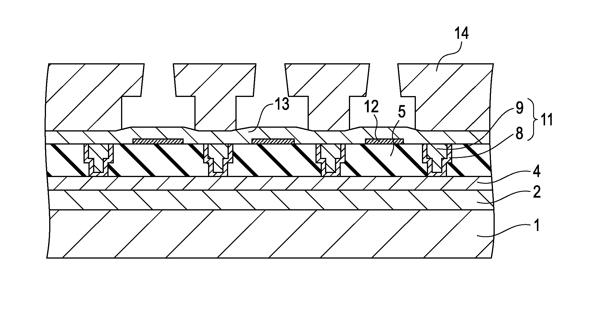
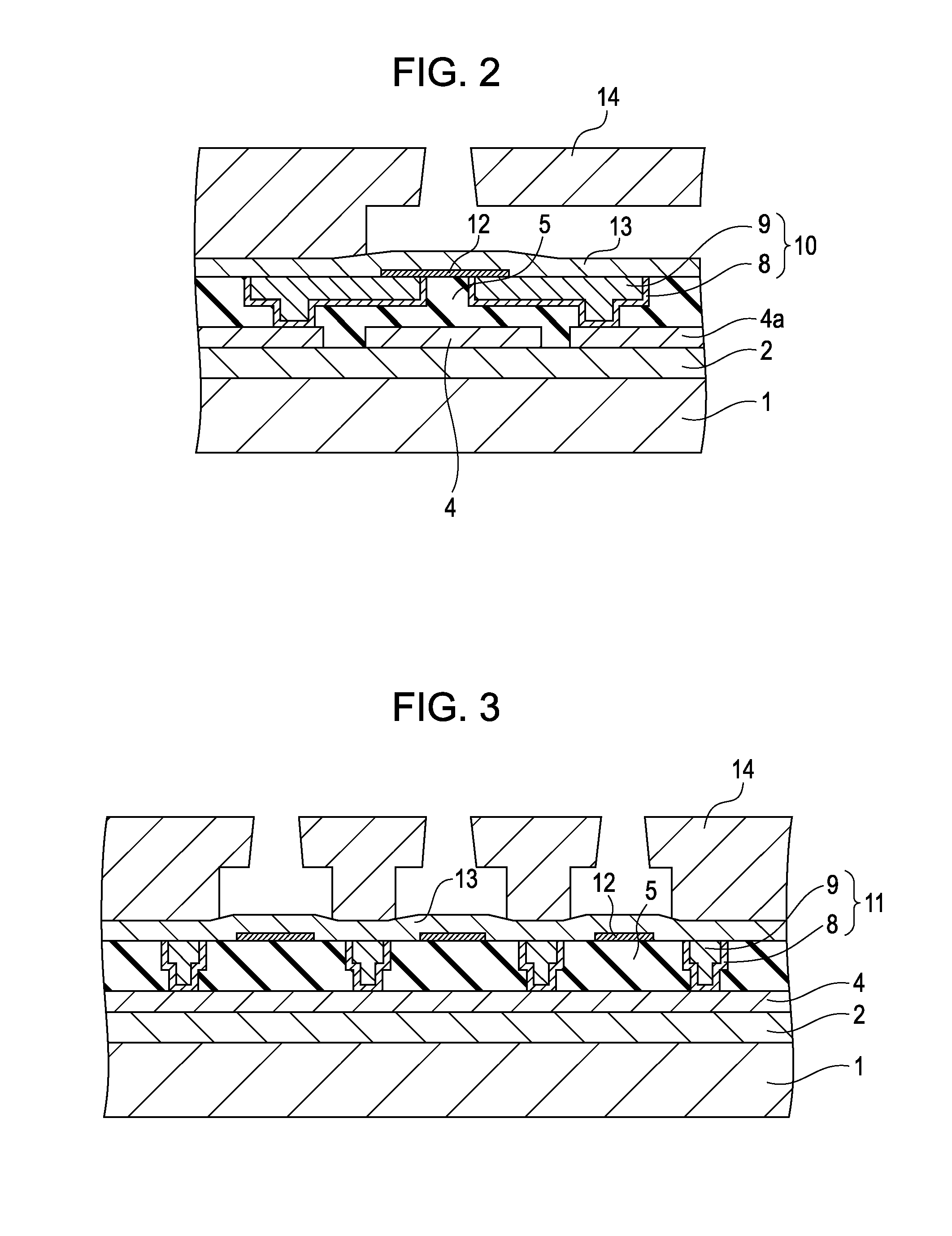
[0038]An embodiment of the present invention will be described with reference to FIGS. 2 and 3. As shown in FIG. 2, an interlayer film 2 composed of boron- and phosphorus-doped SiO2 is disposed at a thickness of 500 nm on a Si substrate 1 provided with active elements, such as transistors (not shown). A heat conduction layer 4 and an electrode layer 4a composed of an Al—Si alloy are disposed at a thickness of 400 nm on the interlayer film 2. An insulating layer 5 composed of SiO2 is disposed at a thickness of 1 μm on the heat conduction layer 4 and the electrode layer 4a. The insulating layer 5 also serves as a heat storage layer that stores the heat of the heating portions 12. The heating portions 12 composed of TaSiN are disposed at a thickness of 50 nm on the insulating layer 5. Both ends of each heating portion 12 are in contact with electrodes 10. The electrodes 10 are in contact with the electrode layer 4a through contact holes provided in the insulating layer 5.

[0039]The elec...

second embodiment

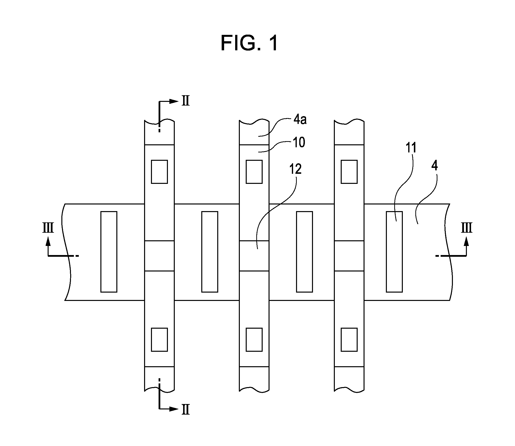
[0053]Examples according to a second embodiment of the present invention are shown in FIGS. 7A and 7B. The structure and the manufacturing method in the second embodiment are the same as those in the first embodiment except for the shape of the heat conduction members 11, and thus, a repeated description thereof will be omitted. As shown in the first embodiment, by providing the heat conduction members 11 as shown in FIG. 1, thermal interference can be prevented. In the case where higher speed is required, adjustment can be made by increasing the volume of the heating portions 12. However, if the distance between each of the heat conduction members 11 and its adjacent heating portion 12 is too small, the insulating layer 5 cannot produce an effect as a heat storage layer, and heat of the heating portion 12 escapes to the heat conduction member 11 before ink is subjected to film boiling. Therefore, it is necessary to locate the heat conduction member 11 at a position at least 1 μm aw...

third embodiment

[0055]Examples according to a third embodiment of the present invention are shown in FIGS. 8A and 8B. The structure and the manufacturing method in the third embodiment are the same as those in the first embodiment except for the shape of the heat conduction members 11, and thus, a repeated description thereof will be omitted.

[0056]FIGS. 8A and 8B are each a schematic plan view showing an end portion of the arrangement of heating portions 12 which are arranged at a predetermined pitch as shown in FIG. 6. In the recording element substrate 1050, since the heating portions 12 are densely located in the central region, heat is more easily stored in the central region than in the end region. When there is a temperature variation between the central region and the end region of the recording element substrate 1050, ink on a heating portion 12 located in the central region is heated faster than ink on a heating portion 12 located in the end region, resulting in a variation in ejection. Su...


PUM

PropertyMeasurementUnit
distanceaaaaaaaaaa
thicknessaaaaaaaaaa
thicknessaaaaaaaaaa

Abstract

A recording element substrate includes a substrate; an insulating layer disposed on the substrate; a plurality of heating portions which are arranged on the insulating layer and which produce thermal energy used to eject a liquid; and a plurality of heat conduction members, each being located between adjacent heating portions with respect to an arrangement direction of the heating portions, the heat conduction members being located between the substrate side principal surface of the insulating layer and the heating portion side principal surface of the insulating layer and having higher thermal conductivity than the insulating layer. The heat conduction members are in contact with a heat conduction layer which has higher thermal conductivity than the insulating layer.

Description

BACKGROUND OF THE INVENTION[0001]1. Field of the Invention[0002]The present invention relates to a recording element substrate configured to perform recording using thermal energy, a method of manufacturing the recording element substrate, and a liquid ejection head.[0003]2. Description of the Related Art[0004]As thermal recording devices in which recording is performed by heating a plurality of heating portions provided therein, sublimation-type recording devices and inkjet-type recording devices are known. In a sublimation-type recording device, recording is performed by a method in which ink on an ink ribbon is melted by heat and transferred onto a recording medium, while in an inkjet-type recording device, recording is performed by a method in which a liquid, such as ink, is subjected to film boiling, thereby ejecting the ink. In these recording devices, in order to diffuse excess heat generated in heating portions, a substrate having high thermal conductivity is used as a recor...

Claims


Application Information

Patent Timeline
Patent Type & Authority Patents(United States)
IPC IPC(8): B41J2/05B41J2/14B41J2/16
CPCB41J2/14129B41J2/1408B41J2/1603B41J2/1632B41J2/1642B41J2/1643B41J2/1646Y10T29/49401
Inventor ISHIDA, YUZURUKOMURO, HIROKAZUSAITO, ICHIROSAKURAI, MAKOTOMATSUI, TAKAHIRO
Owner CANON KK
Why Eureka
Try Eureka