

Automatic delay compensation method and system for sound box device
A technology of automatic compensation and speaker equipment, applied in signal processing, sensor parts, sensors, etc., can solve the problems of delay compensation of speaker equipment and low efficiency of debugging process.
- Summary
- Abstract
- Description
- Claims
- Application Information
AI Technical Summary
Problems solved by technology
Method used
Image

Examples
Embodiment 1
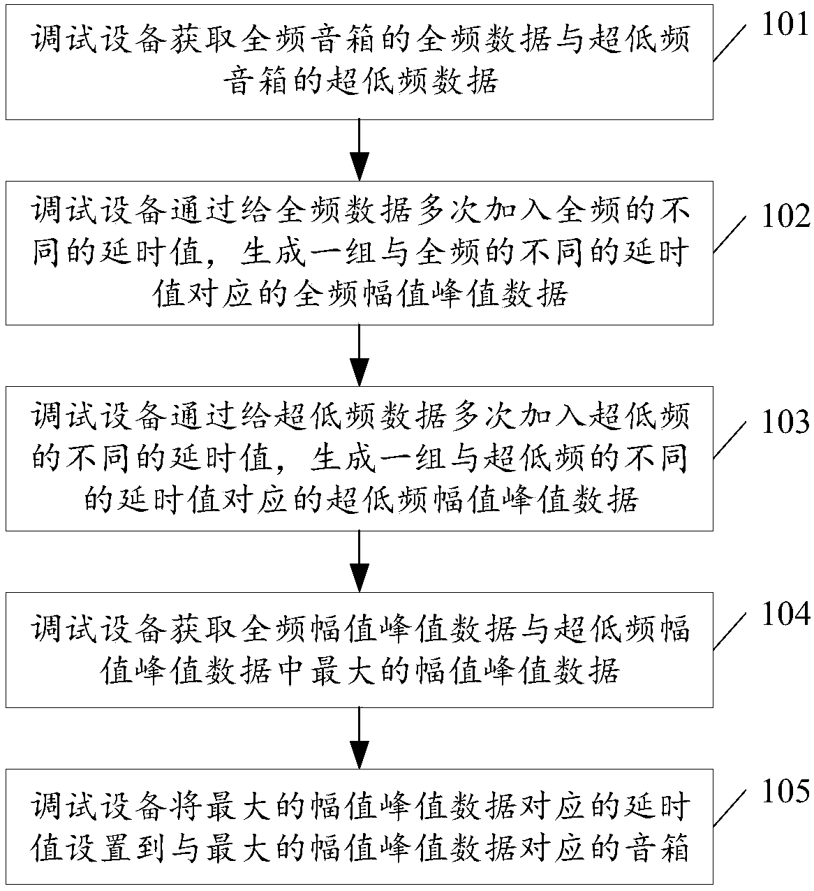
[0087] see figure 1 , figure 1 It is a schematic flowchart of a method for automatically compensating time delay of a speaker device disclosed in an embodiment of the present invention. like figure 1 As shown, the automatic compensation delay method of the speaker device may include the following steps:
[0088] 101. The debugging device acquires the full-frequency data of the full-range speaker and the ultra-low frequency data of the subwoofer.
[0089] In the embodiment of the present invention, the full-frequency speaker can cover the range of sound frequency from 20Hz to 20KHz, and the ultra-low frequency speaker can cover the range of sound frequency from 20Hz to 100Hz. Professional subwoofers are needed to supplement and optimize the playback effect of the speaker system.
[0090] In the embodiment of the present invention, the full-frequency data may be the frequency response curve of the full-frequency speaker, and the ultra-low frequency data may be the frequency ...
Embodiment 2
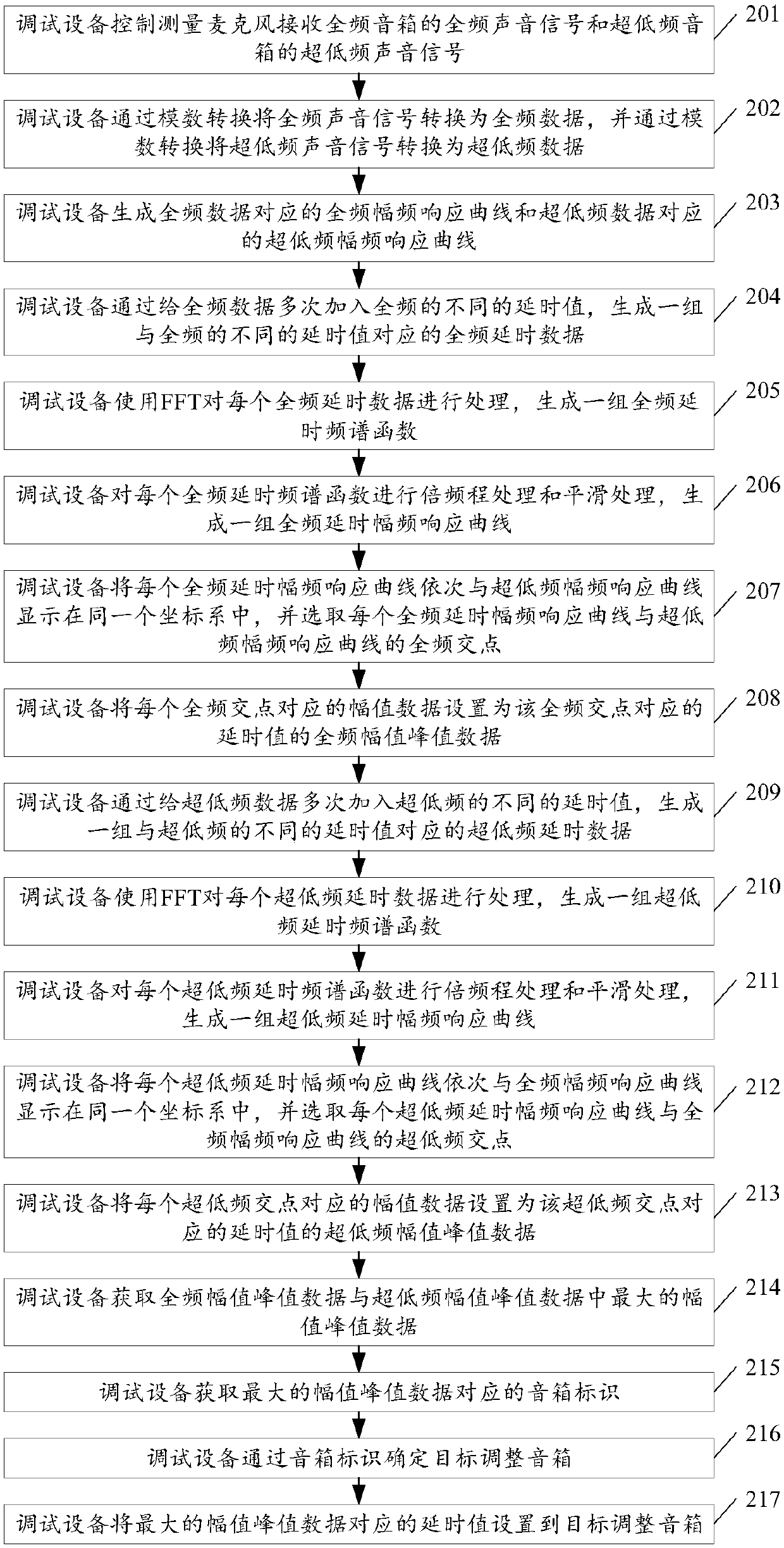
[0120] see figure 2 , figure 2 It is a schematic flowchart of another method for automatically compensating time delay of a speaker device disclosed in an embodiment of the present invention. like figure 2 As shown, the automatic compensation delay method of the speaker device may include the following steps:
[0121] 201. The debugging device controls the measurement microphone to receive the full-range sound signal of the full-range speaker and the ultra-low-frequency sound signal of the ultra-low-frequency speaker.
[0122] In the embodiment of the present invention, the measurement microphone is different from the ordinary microphone. The measurement microphone needs to accurately judge and measure the frequency response, phase, signal-to-noise ratio, and spectrum analysis of the speaker. Therefore, the measurement microphone needs to have extremely high sensitivity. , all-round sound pickup range, balanced and precise frequency response curve and high sound pressure...
Embodiment 3
[0166] see Figure 4 , Figure 4 It is a structural schematic diagram of an automatic compensation delay system for a speaker device disclosed in an embodiment of the present invention. Among them, such as Figure 4 As shown, the system may include a debugging device 400, a full-range speaker 500 and a subwoofer 600, wherein the debugging device 400 includes:
[0167] The first acquiring unit 401 is configured to acquire the full-frequency data of the full-range speaker 500 and the ultra-low frequency data of the subwoofer 600 .
[0168] The first generating unit 402 is configured to generate a set of full-frequency amplitudes corresponding to different full-frequency delay values by adding different full-frequency delay values to the full-frequency data obtained by the first acquisition unit 401 multiple times value peak data.
[0169] In the embodiment of the present invention, the first generating unit 402 can add the same delay value to the full-frequency data mult...
PUM
 Abstract
Description
Claims
Application Information