Gear shaping clamp for flange of transmission

A technology of gear hobbing fixture and transmission, which is applied in the field of workpiece clamping device to achieve the effect of convenient operation

Active Publication Date: 2018-04-24
重庆市乐珐机电有限责任公司
View PDF12 Cites 9 Cited by
  • Summary
  • Abstract
  • Description
  • Claims
  • Application Information

AI Technical Summary

Problems solved by technology

[0005] In order to solve the above problems, the present invention provides a transmission flange gear hobbing fixture to solve the problem that the transmission flange will rotate with the gear hobbing device during the gear hobbing process

Method used


Image

  • Gear shaping clamp for flange of transmission
  • Gear shaping clamp for flange of transmission
  • Gear shaping clamp for flange of transmission

Examples


Embodiment Construction

[0023] The present invention will be described in further detail below by means of specific embodiments:

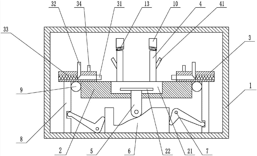
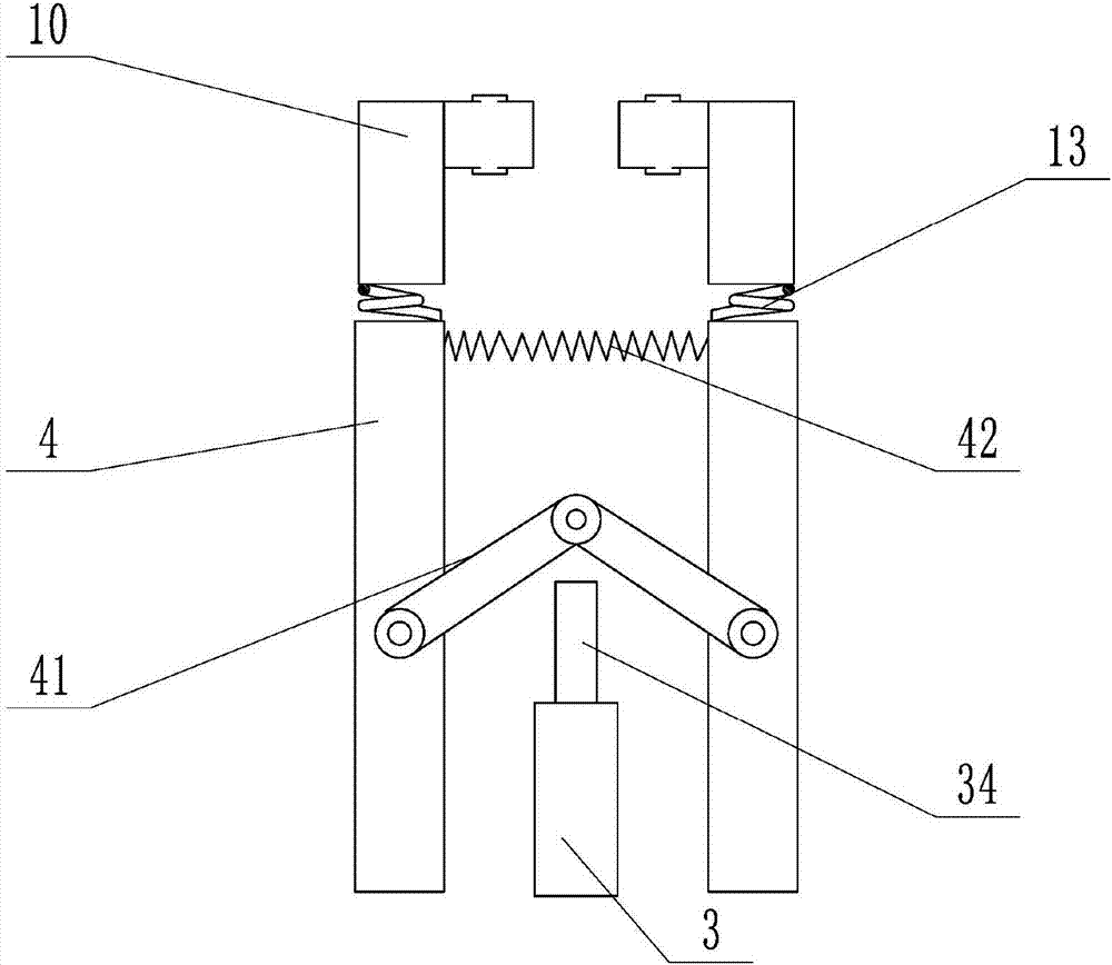
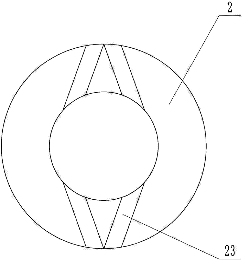
[0024] The reference signs in the drawings of the description include: frame 1, positioning plate 2, positioning notch 21, circular bottom plate 22, chute 23, pressure block 3, horizontal wedge bar 31, vertical wedge bar 32, compression spring 33 , ejector rod 34, fixed rod 4, connecting rod 41, return spring 42, support rod 5, cross bar 6, "V" type lever 7, push rod 8, transmission gear 9, "L" type rod 10, air hole 11 , air bag 12, first torsion spring 13.

[0025] like Figure 1 to Figure 4 As shown, the transmission flange gear hobbing fixture includes a frame 1, a positioning plate 2, a linkage device and two clamping devices. The positioning plate 2 is welded on the frame 1, and the two clamping devices are slidably connected to the positioning plate 2. Above, the linkage device is fixed on the frame 1 and is used to push the clamping device to slide on the positio...


PUM


Abstract

The invention belongs to the field of workpiece clamping devices, and particularly relates to a gear shaping clamp for a flange of a transmission. The gear shaping clamp comprises a positioning disc,and further comprises a clamping device; a positioning spigot is formed in the positioning disc; the clamping device comprises pressing blocks and two fixing rods, wherein the pressing blocks are arranged on the positioning disk in a sliding mode; transverse channels and vertical channels are formed in the pressing blocks; transverse wedge rods are arranged in the transverse channels in a slidingmode and are connected to the inner walls of the pressing blocks through springs; the ends, close to the positioning spigot, of the transverse wedge rods extend out of the pressing blocks; the vertical channels communicate with the outside; vertical wedge rods are arranged in the vertical channels in a sliding mode and abut against the transverse wedge rods; sliding grooves allowing the two fixingrods to slide are formed in the positioning disc; connecting rods are hinged to the middles of the two fixing rods; the free ends of the two connecting rods are hinged; and the vertical wedge rods are used for pushing the hinged joint of the two connecting rods to move. According to the gear shaping clamp, the problem that the flange of the transmission can rotate along with a hobbing device in the gear hobbing machining process can be solved, and the gear shaping clamp is commonly used for fixing the flange plate in the machining process.

Description

technical field [0001] The invention belongs to the field of clamping devices for workpieces, and in particular relates to a gear hobbing clamp for a transmission flange. Background technique [0002] During the process of machining the internal teeth of the transmission flange, due to the large cutting force, the flange moves, which leads to the phenomenon of disordered teeth. In the process of clamping the flange, it takes a long time to find the alignment, which affects the work efficiency and processing. The quality is low, its installation and disassembly are not convenient enough, and the flange plate has many shortcomings such as poor stability during the slotting process. [0003] For this reason, Chinese patent CN204430472U discloses a kind of flange plate gear positioning device, including: a positioning plate, the upper part of the positioning plate is provided with a positioning notch; the flange is placed inside the positioning notch; the middle part of the posi...

Claims


Application Information

Patent Timeline
Patent Type & Authority Applications(China)
IPC IPC(8): B23F23/06
CPCB23F23/06
Inventor 印承霜
Owner 重庆市乐珐机电有限责任公司
Why Eureka
Try Eureka