
A tool grinding and reforming device

A technology for cutting tools and clamping tools, which is applied in the field of tool grinding and modification devices, and achieves the effects of simple structure, convenient use and fast speed.

Active Publication Date: 2019-08-27
JIANGLU MACHINERY & ELECTRONICS GROUP
View PDF6 Cites 0 Cited by
  • Summary
  • Abstract
  • Description
  • Claims
  • Application Information

AI Technical Summary

Problems solved by technology

[0007] The purpose of the present invention is to address the above problems and provide a tool grinding and transformation device to solve the problems of standard tool grinding and non-standard tool regrinding and transformation into other tools

Method used


Image

  • A tool grinding and reforming device

Examples


Embodiment Construction

[0035] In order to enable those skilled in the art to better understand the technical solution of the present invention, the present invention will be described in detail below in conjunction with the accompanying drawings. The description in this part is only exemplary and explanatory, and should not have any limiting effect on the protection scope of the present invention. .

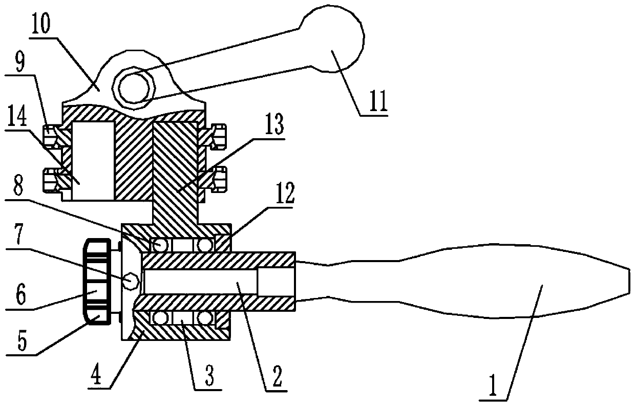
[0036] Such as figure 1 As shown, the specific structure of the present invention is: a tool grinding and reforming device, which is installed on an ordinary machine tool; 2 The tapered roller bearings 8 on the front and rear sides are arranged in the sharpener base 4, and the tapered roller bearings 8 are arranged on the bearing seats at both ends of the hole in the sharpener base 4; the handle 1 and the knife holder The mandrel 2 is connected to the end of the knife mandrel 2 through threads; the knife mandrel 2 is provided with a plurality of indexing positioning holes, and the knife sharpener base...


PUM


Abstract

The invention discloses a cutter repair-grinding and transforming device. The device is installed on a general-purpose machine tool. The device comprises a handle, a cutter clamping mandrel and a cutter sharpener base, the cutter clamping mandrel is arranged in the cutter sharpener base through conical roller bearings on the front side and the rear side, and the conical roller bearings are arranged on bearing seats at the two ends in the hole of the cutter sharpener base; the handle is in threaded connection with the cutter clamping mandrel; and positioning holes are formed in the cutter clamping mandrel, pin holes are formed in the cutter sharpener base, positioning pins penetrate through the pin holes in the cutter sharpener base to be matched with the indexing positioning holes in the cutter clamping mandrel; a base cylindrical shaft is arranged at the upper side end of the cutter sharpener base, a clamp connecting body is arranged at the upper end of the cutter sharpener base, a cylindrical hole matched with the base cylindrical shaft is formed in the clamp connecting body, and an inner hexagonal fastening screw is arranged on the clamp connecting body and is used for locking the base cylindrical shaft. The invention aims to provide the cutter repair-grinding and transforming device which is used for solving the problems of repair-grinding for a standard cutter and regrinding and transforming a non-standard cutter into other cutters.

Description

technical field [0001] The invention relates to the technical field of mechanical processing, in particular to a tool grinding and reforming device. Background technique [0002] In the mechanical processing industry, the cost problem caused by tool wear and scrap is a major problem that directly affects whether the company can improve its benefits. However, today's companies are basically helpless when dealing with similar problems, or use the used tools as waste and repurchase them. For cutting tools, either send the used tools to a professional tool grinding company for grinding or regrinding, and re-coating, resulting in high costs. [0003] Through patent search, there are the following known prior art: [0004] Patent 1: Patent application number: CN201420250615.5, application date: 2014-05-15, publication date: 2014-09-17, discloses a CNC punching and shearing tool grinding fixture, which includes a clamp body, a pressing plate, Fixed rotating core, limit plate and ...

Claims


Application Information

Patent Timeline
Patent Type & Authority Patents(China)
IPC IPC(8): B24B3/00B24B41/06
Inventor 罗军唐志洪刘枢陈灌生向杰
Owner JIANGLU MACHINERY & ELECTRONICS GROUP
Learn More