Conveyor belt puncher

A conveyor belt punching, conveyor belt technology, applied in the direction of metal processing, cleaning methods and tools, cleaning hollow objects, etc., can solve problems such as troublesome, residual blanking of the blanking bucket, difficult cleaning, etc.

Pending Publication Date: 2018-04-24
ZHENJIANG SANWEI CONVEYING EQUIP CO LTD
View PDF0 Cites 3 Cited by
  • Summary
  • Abstract
  • Description
  • Claims
  • Application Information

AI Technical Summary

Problems solved by technology

[0003] In the prior art, the setting of the blanking recovery parts is very simple, and there is only one blanking bucket. When the bucket is full, the blanking bucket will be removed and replaced with a new bucket. Repeated replacement of the blanking bucket will bring troubles in operation, and also It is very troublesome to keep an eye on whether the material in the blanking bucket is full, and there will be residual material in the blanking bucket, which is difficult to clean

Method used


Image

  • Conveyor belt puncher
  • Conveyor belt puncher
  • Conveyor belt puncher

Examples


Embodiment Construction

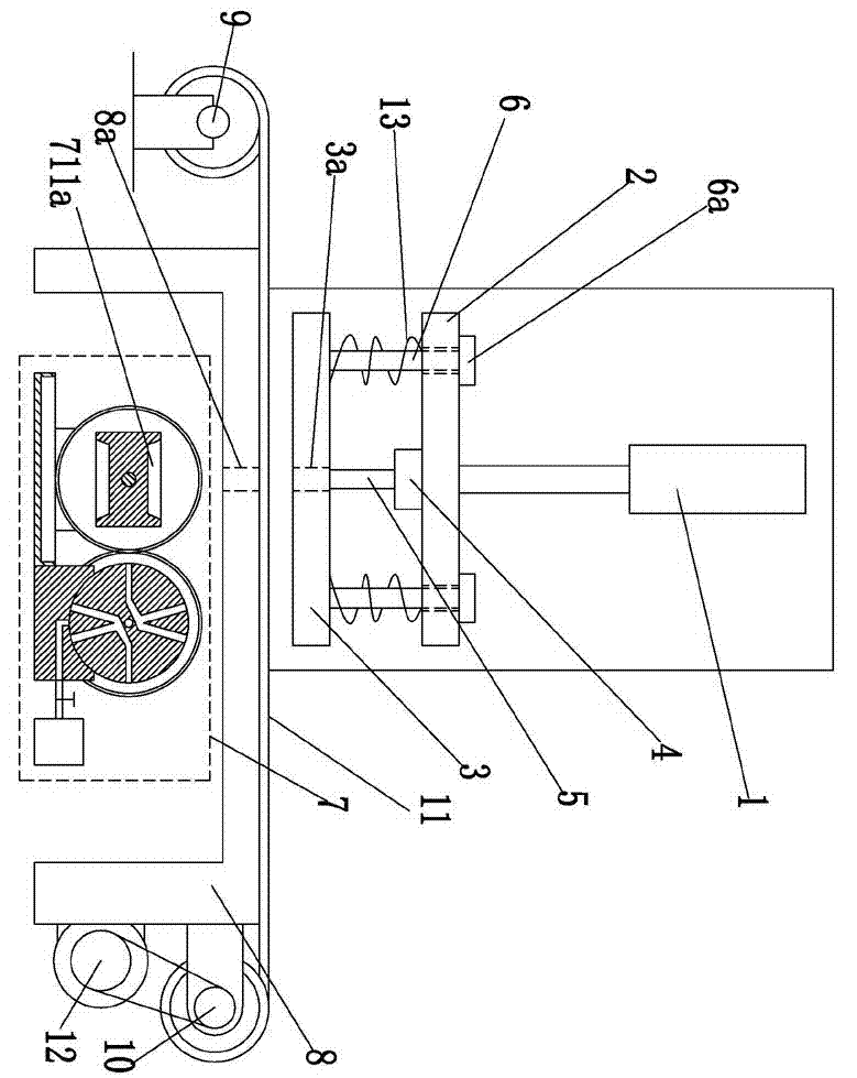
[0021] Such as Figure 1-5 As shown, the conveyor belt punching machine includes a frame 8, a drill bit 5 for drilling holes in the conveyor belt 11, a drilling motor 4 that drives the drill bit 5 to rotate, and a frame mounted on the frame that can be vertically lifted. 8, the buoyancy platform 2 installed together with the drilling motor 4 also includes a stamping drive mechanism 1 that can control the buoyancy platform 2 to carry out vertical lifting, and also includes a conveyor belt 11 for winding the unperforated, The feeding roller 9 that is rotatably installed on the frame 8 also includes a receiving roller 10 that is rotatably installed on the frame 8 for winding the perforated conveyor belt 11, and also includes a receiving roller 10 that is used to drive the The material roller 10 rotates the material receiving motor 12 for receiving material, and also includes a PLC controller 14, and the stamping drive mechanism 1, the drilling motor 4, and the material receiving ...


PUM


Abstract

The invention discloses a conveyor belt punching machine in the technical field of conveyor belt manufacturing, which includes a frame, a drill bit, a drilling motor, a floating platform, a stamping drive mechanism, a material placement roller, and a collection roller, and also includes a driving mechanism for driving the collection roller to carry out The receiving motor that rotates the receiving material also includes a PLC controller, the stamping drive mechanism, the drilling motor, and the receiving motor are all controlled by the PLC controller; the rack is equipped with a blanking hole that is used for blanking and is facing the drill bit. The blanking recovery parts located directly below the blanking holes are installed on the frame, and the blanking recovery parts include transposition motors, driving gears, driven gears, driving shafts, driven shafts, movable receiving seats, collecting basins, and corners. Encoder. The rotary angle encoder can measure the rotation angle of the driven rotating shaft, thereby indirectly monitoring the rotation angle of the movable receiving seat and the number of discharge times of the recovery tank.

Description

technical field [0001] The invention relates to the technical field of conveyor belt manufacturing, in particular to a conveyor belt punching machine. Background technique [0002] At present, the general structure of the conveyor belt drilling machine includes a frame, a drill bit for drilling holes in the conveyor belt, a drilling motor that drives the drill bit to rotate, and a machine that can be vertically lifted and installed on the frame, and The lifting table with the drilling motor installed together also includes a stamping drive mechanism that can control the lifting table to carry out vertical lifting, and also includes a material placement roller that is rotatably installed on the frame for winding the blank conveyor belt, It also includes a rewinding roller that is rotatably installed on the frame for winding the finished product conveyor belt, and a rewinding motor used to drive the rewinding roller to rotate and rewind, and also includes a PLC controller, a s...

Claims


Application Information

Patent Timeline
Patent Type & Authority Applications(China)
IPC IPC(8): B26F1/16B26D7/02B26D7/00B26D5/00B08B9/093
CPCB26F1/16B08B9/093B26D5/00B26D7/00B26D7/025B26D2007/0018
Inventor 李光千
Owner ZHENJIANG SANWEI CONVEYING EQUIP CO LTD
Why Eureka
Try Eureka