
Plastic production stirring and mixing device with smashing function

A technology of mixing and stirring devices, which is applied in the field of mixing and mixing devices for plastic production, can solve the problems of low work efficiency, difficulty in fully mixing, time-consuming and laborious, etc., and achieve the goal of improving the quality of stirring and mixing, speeding up the speed of stirring and mixing, and speeding up the mixing rate Effect

Inactive Publication Date: 2018-04-24
ZHENGZHOU HAOEN ELECTRONICS INFORMATION TECH CO LTD
View PDF4 Cites 4 Cited by
  • Summary
  • Abstract
  • Description
  • Claims
  • Application Information

AI Technical Summary

Problems solved by technology

[0002] The plastic processing technology is to use various plastics as raw materials, add various additives, heat and pressurize, improve the performance of plastics, and enhance the toughness, strength, fire resistance and other properties of plastic particles; the mixer is a kind of mixer with blades The shaft rotates in a cylinder or tank to stir and mix various raw materials to make it a mixture or a machine with a suitable consistency; in the plastic processing process, it is necessary to mix and stir plastic raw materials and additives, and a mixer is required for mixing. At present, when the mixers on the market are mixing raw materials, some raw materials have large particles, which are difficult to mix evenly and fully. Therefore, it is necessary to perform preliminary crushing on the raw materials and then mix them. Existing devices also exist. The mixing of plastic raw materials is not uniform, the work efficiency is low, and the quality is poor. It needs to be stirred several times to mix thoroughly, which is time-consuming and labor-intensive.

Method used


Image

  • Plastic production stirring and mixing device with smashing function
  • Plastic production stirring and mixing device with smashing function
  • Plastic production stirring and mixing device with smashing function

Examples


Embodiment Construction

[0017] The technical solution of this patent will be further described in detail below in conjunction with specific embodiments.

[0018] Embodiments of the present patent are described in detail below, examples of which are shown in the drawings, wherein the same or similar reference numerals designate the same or similar elements or elements having the same or similar functions throughout. The embodiments described below by referring to the figures are exemplary and are only used for explaining the patent, and should not be construed as limiting the patent.

[0019] In the description of this patent, it is to be understood that the terms "center", "upper", "lower", "front", "rear", "left", "right", "vertical", "horizontal", The orientation or positional relationship indicated by "top", "bottom", "inner", "outer", etc. is based on the orientation or positional relationship shown in the drawings, and is only for the convenience of describing this patent and simplifying the des...


PUM


Abstract

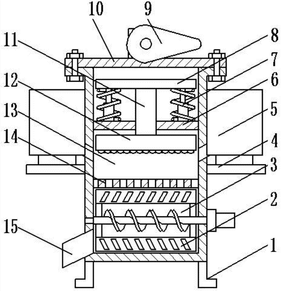
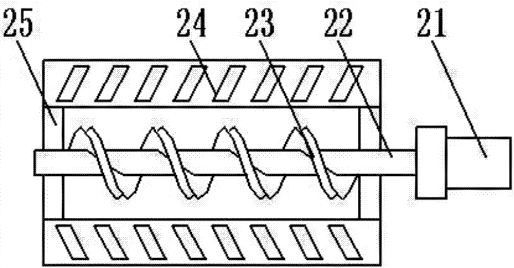
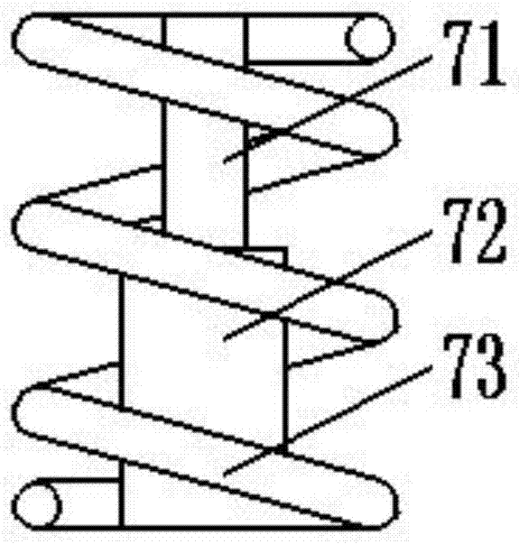
The invention provides a plastic production stirring and mixing device with a smashing function, and belongs to the technical field of chemical engineering. The device comprises supporting legs, and astirring and mixing chamber is arranged on the tops of the supporting legs; the supporting legs are welded to the bottom of the stirring and mixing chamber; a stirring device is arranged in the stirring and mixing chamber; a material discharging pipe is arranged on the left side of the stirring and mixing chamber; the material discharging pipe is welded to the left side of the stirring and mixingchamber; a filter plate is arranged on the top of the stirring and mixing chamber; a smashing cavity is formed in the top of the filter plate; the smashing cavity is internally provided with a smashing block, a vertical connection rod, a transverse supporting rod, reset devices and a baffle. The device is simple in structure and reasonable in design; due to the arrangement of a material inlet box, materials are easily gathered and input into the smashing cavity; under the action of a smashing block, the materials are smashed, the smashed materials are uniformly input into the stirring and mixing chamber through the filter plate and then stirred and mixed, and the material stirring and mixing speed is greatly increased.

Description

technical field [0001] The invention relates to a chemical production equipment, in particular to a stirring and mixing device for plastic production with a crushing function. Background technique [0002] The plastic processing technology is to use various plastics as raw materials, add various additives, heat and pressurize, improve the performance of plastics, and enhance the toughness, strength, fire resistance and other properties of plastic particles; the mixer is a kind of mixer with blades The shaft rotates in a cylinder or tank to stir and mix various raw materials to make it a mixture or a machine with a suitable consistency; in the plastic processing process, it is necessary to mix and stir plastic raw materials and additives, and a mixer is required for mixing. At present, when the mixers on the market are mixing raw materials, some raw materials have large particles, which are difficult to mix evenly and fully. Therefore, it is necessary to perform preliminary c...

Claims


Application Information

Patent Timeline
Patent Type & Authority Applications(China)
IPC IPC(8): B29B13/10B29B7/14B29B7/16B29B7/24B29B7/26B29B7/22
Inventor 刘继军
Owner ZHENGZHOU HAOEN ELECTRONICS INFORMATION TECH CO LTD
Learn More