Cable type tire bead and tire

A bead and cable type technology, applied in tire parts, bead, textile cables, etc., can solve the problems of reducing the service life of the bead, large arrangement gap, low effective strength of the bead, etc., to extend the life of the bead, The effect of improving section strength and reducing stress concentration

A bead and cable type technology, applied in tire parts, bead, textile cables, etc., can solve the problems of reducing the service life of the bead, large arrangement gap, low effective strength of the bead, etc., to extend the life of the bead, The effect of improving section strength and reducing stress concentration

CN107953728AActive Publication Date: 2018-04-24JIANGSU XINGDA STEEL TYPE CORD

Image

  • Cable type tire bead and tire
  • Cable type tire bead and tire
  • Cable type tire bead and tire

Examples


Embodiment 1

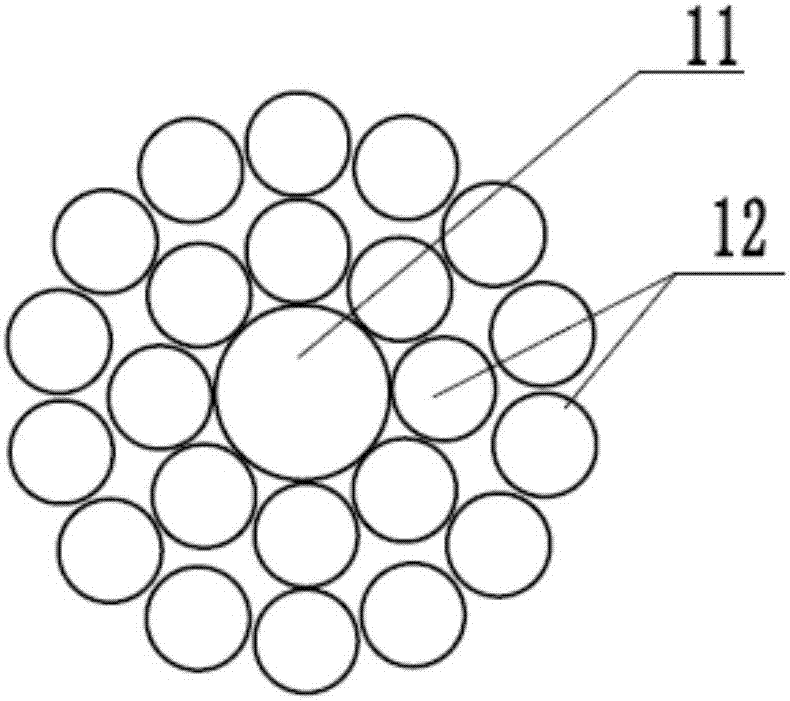
[0041] Such as Figure 4 As shown, a cable-shaped bead has a specification of 1×φ5.00+(10)×(2.00×1.80), the core ring steel wire 31 is a round steel wire with a diameter of 5.00mm, and the outer winding steel wire 32 is a flat steel wire. The long axis is 2.00mm, the long axis is perpendicular to the radial direction of the bead section, the short axis is 1.80mm, and the short axis is parallel to the radial direction of the bead section. As shown in Table 1, compared with the prior art 1, the effective section strength of the cable bead in this embodiment is increased by 3.18%, the fatigue fracture retention is increased by 4.26%, and the cross-sectional diameter of the bead is reduced 3.78%.

[0042] Table 1

[0043]

[0044]

Embodiment 2

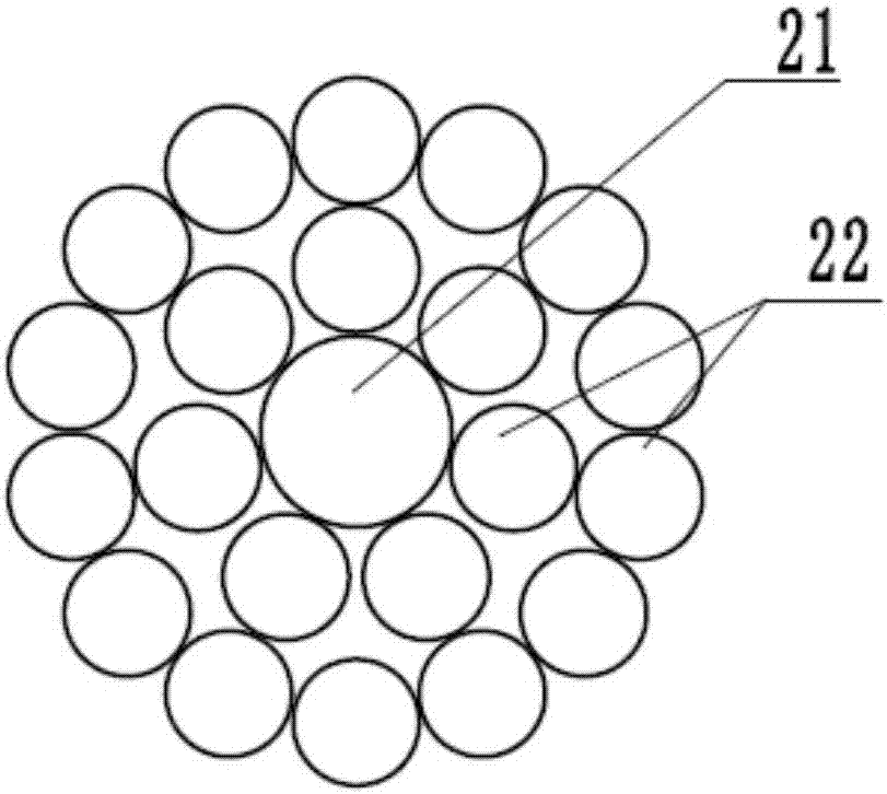
[0046] Such as Figure 5 and 6 As shown, a cable-shaped bead has a specification of 1×φ3.00+(7+12)×(1.98×1.70), the core ring steel wire 41 is a round steel wire with a diameter of 3.00mm, and the outer winding steel wire 42 is flat The steel wire has a long axis of 1.98 mm, the long axis is perpendicular to the radial direction of the bead section, and its short axis is 1.70 mm, and the short axis is parallel to the radial direction of the bead section. Along the radial direction of the bead section, the winding direction of the outer winding wire 42 of the first layer is the S direction, and the winding direction of the outer winding wire 42 of the second layer is the Z direction. As shown in Table 2, compared with prior art 2, the effective section strength of the cable bead in this embodiment is increased by 2.16%, the fatigue fracture retention is increased by 7.95%, and the cross-sectional diameter of the bead is reduced 2.64%.

Embodiment 3

[0048] The difference from Example 2 is that the winding direction of the outer winding wire of the first layer is the S direction from the inside to the outside along the radial direction of the bead section, and the winding direction of the outer winding wire of the second layer is the S direction. As shown in Table 2, compared with prior art 2, the effective section strength of the cable bead in this embodiment is increased by 2.16%, the fatigue fracture retention is increased by 7.95%, and the cross-sectional diameter of the bead is reduced 2.64%.

[0049] Table 2

[0050]


PUM

PropertyMeasurementUnit
lengthaaaaaaaaaa
lengthaaaaaaaaaa
diameteraaaaaaaaaa

Abstract

The invention discloses a cable type tire bead and a tire. The cable type tire bead includes a core coil steel wire located at the middle position of the tire bead and at least one layer of outer winding steel wires wound around the outside of the core coil steel wire. All layers of the outer winding steel wires uniformly wind in the circumferential direction of the core coil steel wire. The cabletype tire bead is characterized in that a section of the outer winding steel wires is a flat surface with a long axis and a minor axis, the long axis is vertical to the radial direction of a sectionof the tire bead, and the minor axis is parallel to the radial direction of a section of the tire bead; the outer winding steel wires are in surface contact with the core coil steel wire; and when atleast two layers of the outer winding steel wires are arranged, line contact is formed between the outer winding steel wires. The cable type tire bead and the tire has the beneficial effects that thearrangement gap and the section size can be reduced, the section intensity is increased, the stress concentration in the tire bead is reduced, and the service life of the tire bead is prolonged.

Description

technical field [0001] The invention belongs to the technical field of rubber products, and in particular relates to a cable bead and a tire. Background technique [0002] The tire is generally composed of a crown, a sidewall, and a bead. The bead is tightened on the rim, providing a support point for the tire carcass, and carrying the outward expansion pressure of the carcass and the lateral force of the tire during turning. Therefore, the tire The ring is required to have high strength, compact and firm structure, stable and not easy to deform. [0003] The cable-shaped bead is a bead with a circular cross-section. The utility model patent with the publication number CN202071638U provides a special-shaped bead wire. Compared with the hexagonal bead, it has no sharp corners and is not easy to form stress concentration. The carcass cord will not produce cutting effect, which can play a better role in protecting the tire. [0004] The invention patent with publication numbe...

Claims


Application Information

Patent Timeline
24 Apr 2018
Publication
CN107953728A
IPC
B60C15/04
CPC
B60C15/04; B60C2015/048; B60C2015/046; D07B1/062; D07B1/0633; D07B2201/2003; D07B2201/203; D07B2201/2037
Inventors
刘祥; 苗为钢