Shuttle weft insertion apparatus with tracks

A technology of weft insertion device and track, which is applied in the direction of textile, textile, papermaking, loom, etc., can solve the problems of low production efficiency, manual shuttle picking, and abnormal weaving, etc., and achieve safe and fast production, ensure stability, and large weft storage capacity Effect

Active Publication Date: 2018-04-24
苏州硕海机电科技有限公司
View PDF8 Cites 2 Cited by
  • Summary
  • Abstract
  • Description
  • Claims
  • Application Information

AI Technical Summary

Problems solved by technology

According to the characteristics of composite materials and medical materials and the requirements of weaving technology, when weaving composite multi-layer prefabricated parts and artificial blood vessel tubular fabrics on medical textiles, due to the non-abrasion resistance of the fibers, the breakage rate is too high, and the efficiency is extremely low or even It cannot be weaved normally; and because the weaving of multi-layer prefabricated parts of composite materials requires the integrity of the prefabricated parts, the weft yarn must be continuously woven; and the current production of prefabricated parts made of composite materials is mostly manual picking, and the production efficiency is very high. Low

Method used


Image

  • Shuttle weft insertion apparatus with tracks
  • Shuttle weft insertion apparatus with tracks
  • Shuttle weft insertion apparatus with tracks

Examples


Embodiment 1

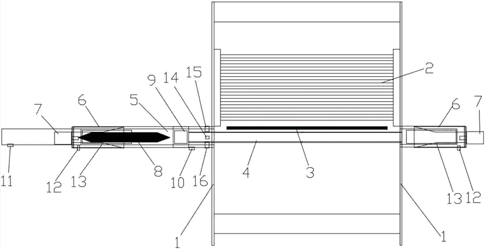
[0019] Such as figure 1 As shown, this embodiment provides a shuttle weft insertion device with rails, which includes a fixed bracket 1, a U-shaped guide rail 4, a heald frame 2, a steel reed 3, a linear guide 9, and a rail telescopic drive mechanism 5. Shuttle stop mechanism 6, shuttle mechanism 7, shuttle 8, U-shaped guide rail front dead center detection device 10, U-shaped guide rail rear dead center detection device 11, shuttle in-position detection device 12, shuttle box cover 13, U-shaped guide rail Under-track guide wheel bearing 14, U-shaped guide rail inner guide wheel bearing 15, U-shaped guide rail outer guide wheel bearing 16; the U-shaped guide rail 4 not only includes the front end rail into the shed, but also when the shuttle is stationary Shuttle box position; the bottom of the U-shaped guide rail 4 near the tail end and the sliding block of the linear guide 9 are fixed, and the lower U-shaped guide rail bearing 14 and the inner guide wheel of the U-shaped guide...

Embodiment 2

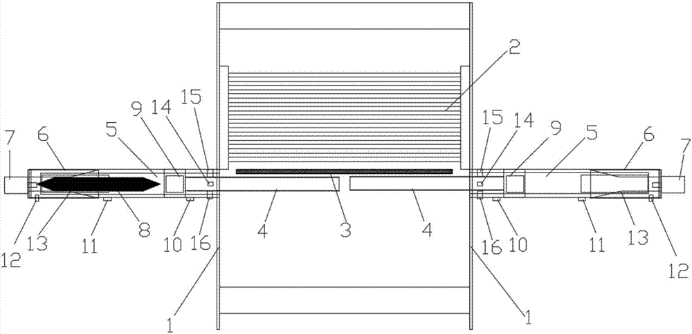
[0022] Such as figure 2 As shown, this embodiment provides a shuttle weft insertion device with rails, which includes a fixed bracket 1, a U-shaped guide rail 4, a heald frame 2, a steel reed 3, a linear guide 9, a rail telescopic structure 5, a stop Shuttle mechanism 6, shuttle mechanism 7, shuttle 8, U-shaped guide rail front dead center detection device 10, U-shaped guide rail rear dead center detection device 11, shuttle in-position detection device 12, shuttle box cover 13, U-shaped guide rail Lower guide wheel bearing 14, U-shaped guide rail inner guide wheel bearing 15, U-shaped guide rail outer guide wheel bearing 16; the U-shaped guide rail 4 is on one side of the loom, which includes the front end rail into the shed , It is the position of the shuttle box when the shuttle is stationary; the sliding block fixed under the U-shaped guide rail 4 described in the bracket 1 near the tail end and the linear guide 9 is fixed, and the lower U-shaped guide rail is located near...


PUM


Abstract

The present invention relates to a shuttle weft insertion apparatus with tracks. The shuttle weft insertion apparatus with tracks comprises a fixed support, heald frames, a reed, a shuttle box and a picking mechanism; The fixed support is also provided with telescoping guide tracks having a non-closed shaped cross section, track telescoping driving mechanisms and linear guide rails; each telescoping guide track comprises a front track entering a shed; a position, close to the tail end, of each telescoping guide track is fixed to a sliding block of the corresponding linear guide rail; and the track telescoping driving mechanisms are fixed to the fixed support, and a piston end of each track telescoping driving mechanism is connected with the tail end of the corresponding telescoping guide track via a connecting piece. According to the shuttle weft insertion apparatus with tracks, upper and lower layer warp yarns in the shed are prevented from extrusion and friction, the shuttle is a conventional large shuttle, the weft storage amount is large, the shuttle is not required to be replaced frequently, and stability of the shuttle flying in the tracks is ensured. When multilayer weavingof composite materials is carried out, weaving efficiency is high, and safe and convenient production can be provided for automatic picking and weft insertion modes of weaving of multilayer prefabricated components of composite materials.

Description

Technical field [0001] The invention relates to the field of textile machinery, in particular to a shuttle weft insertion device with a track. Background technique [0002] The shuttle weft insertion device of the conventional loom is a conventional single-layer fabric weaving method. The weft is introduced into the shed by the shuttle. The shuttle is used as both a weft inserter and a weft accumulator. The shuttle enters from one end of the shed and exits from the other end of the shed. The shuttle flies freely in the shed. It is a relative movement along the sley. . The shuttle is the movement of the lower yarn rolled in the shed, which will cause squeeze and friction on the warp yarn during the movement. According to the characteristics of composite materials and medical materials and the requirements of weaving technology, when weaving composite material multilayer preforms and artificial blood vessel tubular fabrics on medical textiles, due to the non-abrasion resistance o...

Claims


Application Information

Patent Timeline
Patent Type & Authority Applications(China)
IPC IPC(8): D03D45/50
CPCD03D45/50Y02A40/25
Inventor 魏东旭常丽娜杨峰郭佳郭志
Owner 苏州硕海机电科技有限公司
Why Eureka
Try Eureka