Exhaust structure of compressor and compressor

A compressor exhaust and exhaust pipe technology, applied in the direction of machines/engines, mechanical equipment, liquid fuel engines, etc., can solve the problems of large noise, large fluid noise, and more mixing, and achieve the effect of improving oil separation efficiency

Pending Publication Date: 2018-04-24
GREE ELECTRIC APPLIANCES INC
View PDF2 Cites 4 Cited by
  • Summary
  • Abstract
  • Description
  • Claims
  • Application Information

AI Technical Summary

Problems solved by technology

[0003] In the exhaust structure of the compressor, the exhaust pipe is directly arranged horizontally, and the oil and gas are separated only when they pass through the filter, and there is only one separation effect; at the same time, the exhaust port of the exhaust pipe is close to the position of the lower oil tank, and a large amount of gas It will pass through the lower part of the filter screen; the oil-filtered refrigerant gas passing through the lower part will entrain the oil droplets in the oil tank at the bottom and mix together, resulting in more refrigerant gas discharged from the compressor exhaust port. oil droplets
[0004] At the same time, due to the periodic connection between the compression cavity and the exhaust cavity during the compression process, the fluid discharged from the exhaust port presents periodic pressure fluctuations, resulting in large fluid noise
In this structure, the exhaust port is directly connected to the exhaust cavity, and the noise will also be directly transmitted to the exhaust cavity, resulting in a large noise

Method used


Image

  • Exhaust structure of compressor and compressor

Examples


Embodiment Construction

[0019] The present invention will be described in further detail below in conjunction with the accompanying drawings and specific embodiments, but not as a limitation of the present invention.

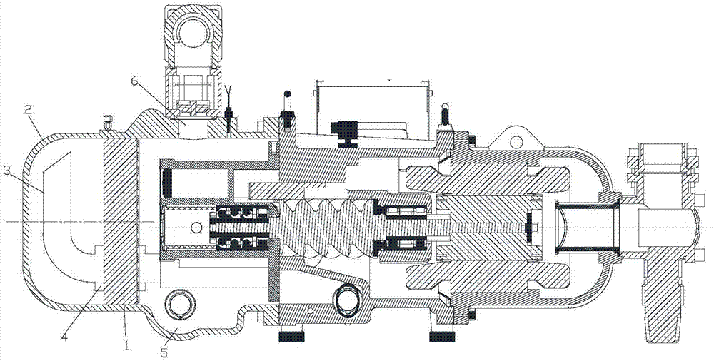
[0020] see in conjunction figure 1 As shown, according to the embodiment of the present invention, the compressor exhaust structure includes an oil filter screen 1, an oil separator barrel 2 and an exhaust pipe 3, and the exhaust pipe 3 extends into the cavity formed by the oil separator screen 1 and the oil separator barrel 2 , the exhaust pipe 3 bends upwards in the cavity.

[0021] Since the exhaust pipe 3 is bent upward in the cavity, the exhaust port of the exhaust pipe 3 can be kept away from the bottom oil tank 5, thereby preventing the refrigerant gas discharged from the exhaust pipe 3 from sweeping the oil droplets at the bottom and improving the oil separation efficiency.

[0022] Preferably, the exhaust port of the exhaust pipe 3 faces the side wall or bottom wall of the oi...


PUM


Abstract

The invention discloses an exhaust structure of a compressor and the compressor. The exhaust structure of the compressor comprises an oil separation filter net (1), an oil separation barrel (2) and anexhaust pipe (3); and the exhaust pipe (3) extends into a cavity formed by the oil separation filter net (1) and the oil separation barrel (2), and is upwards bent in the cavity. The exhaust structure of the compressor can prevent refrigerant gas, exhausted by the exhaust pipe, from sweeping bottom oil drops to improve the oil separation efficiency.

Description

technical field [0001] The invention relates to the technical field of compression equipment, in particular to a compressor exhaust structure and a compressor. Background technique [0002] In the existing built-in oil separation screw compressor oil separation structure, the refrigerant enters the cavity between the oil separation filter screen and the oil separation barrel after being discharged from the exhaust pipe. After the refrigerant and oil mixture is filtered through the oil filter, the gas is discharged from the compressor through the compressor exhaust port, and the oil droplets filtered out by the filter are deposited at the bottom, and then flow back into the oil tank. [0003] In the exhaust structure of the compressor, the exhaust pipe is directly arranged horizontally, and the oil and gas are separated only when they pass through the filter, and there is only one separation effect; at the same time, the exhaust port of the exhaust pipe is close to the positi...

Claims


Application Information

Patent Timeline
Patent Type & Authority Applications(China)
IPC IPC(8): F04C29/12F04C29/02
CPCF04C29/026F04C29/12
Inventor 李磊曾慧王晨光汤雁翔陈红陈喜民陈志虎邹先平
Owner GREE ELECTRIC APPLIANCES INC
Why Eureka
Try Eureka