A synchronization device and test system for non-periodic trigger test of DC power transmission converter valve
A non-periodic triggering, DC transmission technology, applied in the direction of testing dielectric strength, etc., can solve the problem of inaccurate and scattered synchronization signal acquisition, and achieve the effect of accurate and reliable trigger conduction
- Summary
- Abstract
- Description
- Claims
- Application Information
AI Technical Summary
Problems solved by technology
Method used
Image
Examples
Embodiment Construction
[0028] Embodiment of aperiodic trigger test system for DC transmission converter valve
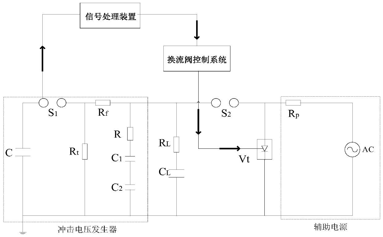
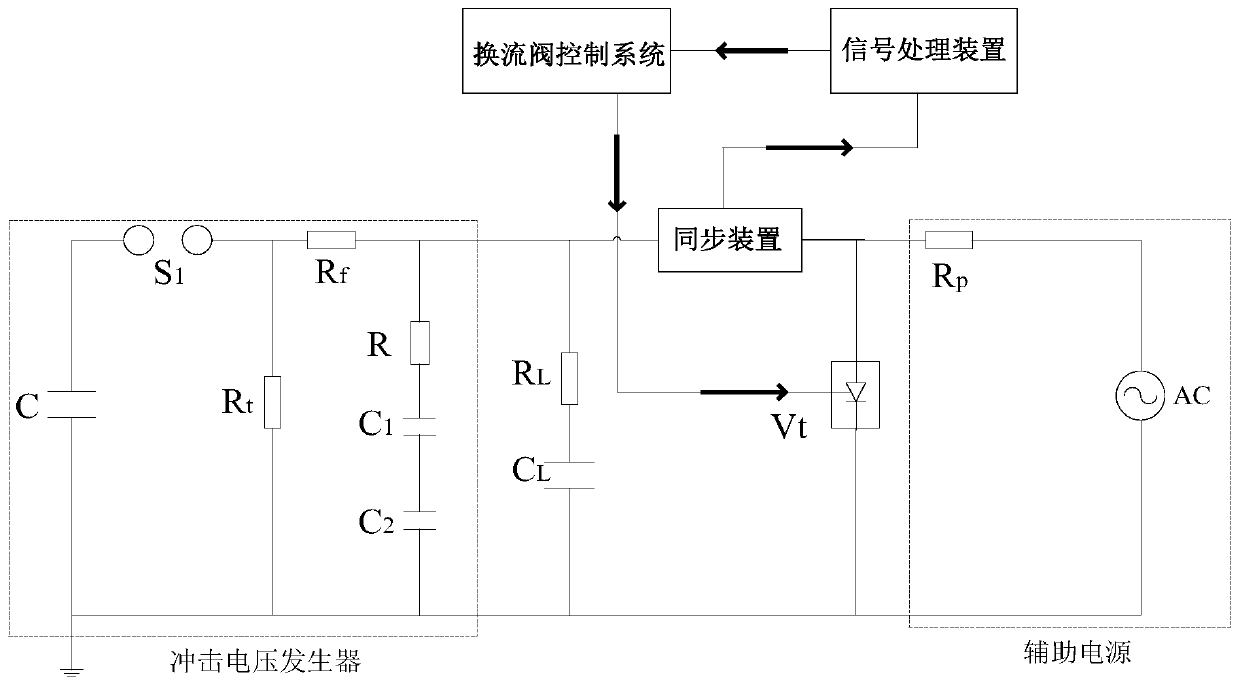
[0029] Such as figure 2 As shown, the output voltage of the impulse voltage generator is connected to the non-periodical triggering test circuit of the DC transmission converter valve. The test circuit is connected with the tested DC transmission converter valve Vt in series. In addition, other circuit structures may also be involved in the circuit , since these circuit structures have nothing to do with the inventive point of the present invention, they will not be described in detail here.
[0030] This embodiment provides a non-periodic trigger test system for a direct current transmission converter valve, which is used to obtain a synchronization signal required for the test, and to perform trigger control of the converter valve according to the obtained synchronization signal. Therefore, if figure 2As shown, the test system mainly includes two parts, namely the synchronization dev...
PUM
 Abstract
Description
Claims
Application Information
 - R&D
- Intellectual Property
- Life Sciences
- Materials
- Tech Scout
- Unparalleled Data Quality
- Higher Quality Content
- 60% Fewer Hallucinations
Browse by: Latest US Patents, China's latest patents, Technical Efficacy Thesaurus, Application Domain, Technology Topic, Popular Technical Reports.
© 2025 PatSnap. All rights reserved.Legal|Privacy policy|Modern Slavery Act Transparency Statement|Sitemap|About US| Contact US: help@patsnap.com


