
Wire joint protective device

A technology of protection device and wire joint, which is applied in the direction of clamping/spring connection, etc., can solve problems such as leakage, safety accidents, and wet terminals, so as to ensure personal safety, prevent wires from hanging down, and facilitate fixed installation.

Pending Publication Date: 2018-04-24
重庆腾盛电线电缆有限公司
View PDF0 Cites 0 Cited by
  • Summary
  • Abstract
  • Description
  • Claims
  • Application Information

AI Technical Summary

Problems solved by technology

This method is a waste of time when connecting, and it is not safe. After a long time of use, the terminal will be wet and leak electricity, causing safety accidents
And the electric glue is easy to fall off after being exposed to moisture, resulting in the fallen wires often falling naturally on the wall or the ground, which will pose a great threat to personal safety

Method used


Image

  • Wire joint protective device
  • Wire joint protective device
  • Wire joint protective device

Examples


Embodiment Construction

[0016] The following will clearly and completely describe the technical solutions in the embodiments of the present invention with reference to the accompanying drawings in the embodiments of the present invention. Obviously, the described embodiments are only some, not all, embodiments of the present invention. Based on the embodiments of the present invention, all other embodiments obtained by persons of ordinary skill in the art without making creative efforts belong to the protection scope of the present invention.

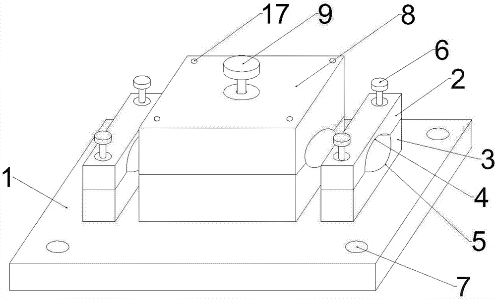
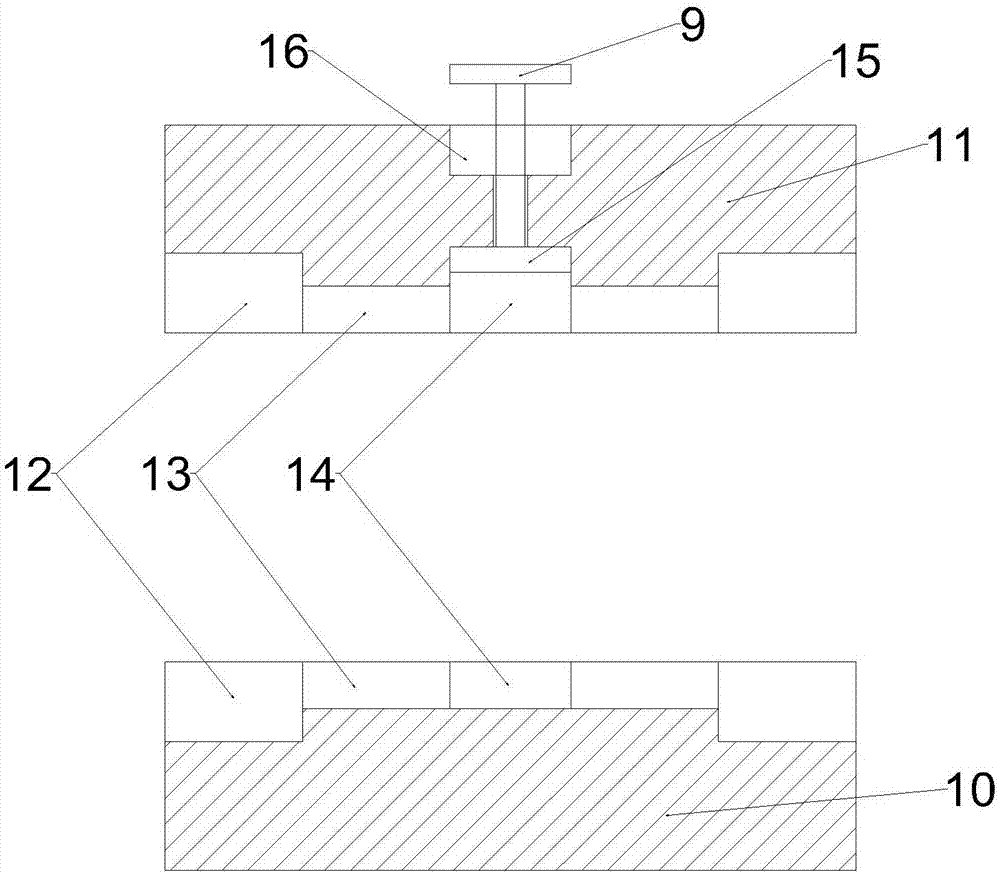
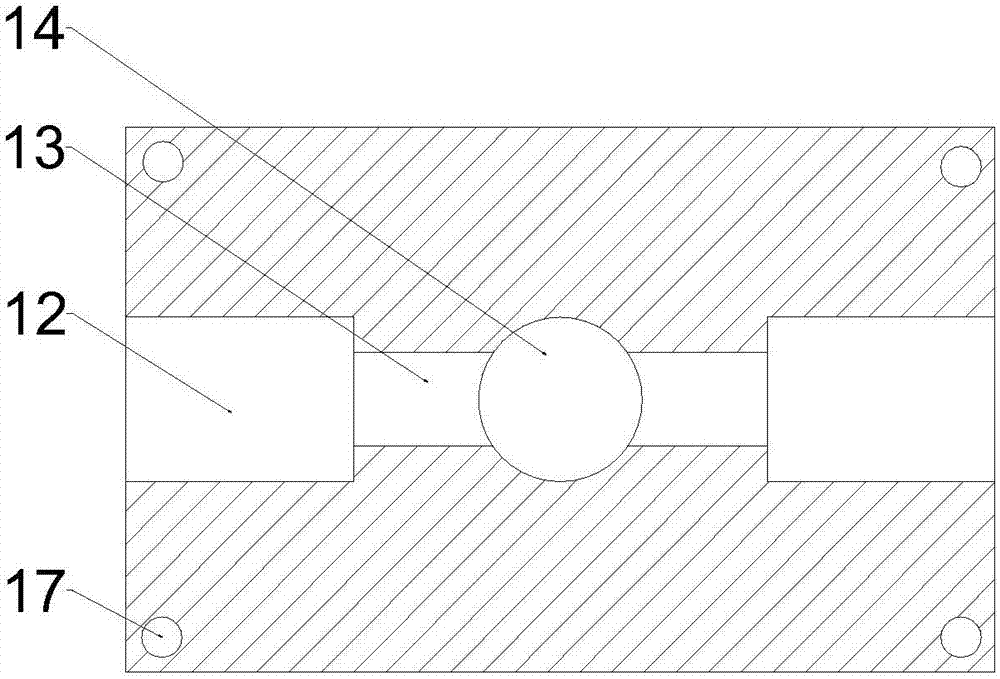
[0017] Such as Figure 1-Figure 3 Shown: a wire joint protection device, including a base 1, a clamping device, a joint box 8 and a compression screw 9, the four corners of the base 1 are provided with mounting holes 7 for easy installation. Described base 1 is provided with clamping device, and described clamping device is left and right two, and structure is identical, and described clamping device comprises upper clamping part 2, lower clamping part 3 and c...


PUM


Abstract

A wire joint protective device comprises a pedestal, clamping devices, a joint box and a compaction screw; four corners of the pedestal are provided with easy-to-mount mounting holes; the clamping device comprises an upper clamping member, a lower clamping member and a clamping screw; the lower clamping member is arranged above the pedestal, and the middle portion is provided with a lower groove;two ends of the upper clamping member are fixed above the lower clamping member through the clamping screw; the upper clamping member is provided with an upper groove matched with the lower groove; the joint box is arranged between the left and right clamping devices, and comprises an upper box, a lower box and the compaction screw; the center of the attaching surface between the upper and lower boxes is provided with a cylindrical joint groove; two ends of the joint groove are connected with a wire duct; the other end of the wire duct is connected with a line slot; the line slot, the wire duct and the joint groove are connected. A pressure plate is arranged in the joint groove of the upper box; the compaction screw is arranged above the pressure plate; the upper box is also provided witha compaction groove matched with the compaction screw.

Description

technical field [0001] The invention relates to the technical field of wire production, in particular to a wire joint protection device. Background technique [0002] The wire connector is also called the wire head, and its main function is to keep the line unobstructed and ensure the insulation level of the wire connector so that it can run safely and reliably. When the distance between the two places is long, it cannot be connected by a single wire, but several wires can only be connected in series, so a butt joint needs to be set between the two wires. And along with the increase of household appliances, new wires are laid, or the original wires are aging and replaced with new wires. New connections of wires will occur, so new wire joints will appear. The insulation layer is torn off to expose the internal wires, then the metal wires are twisted together, and the outside is wrapped with insulating tape. This method wastes time when connecting, and it is not safe. The te...

Claims


Application Information

Patent Timeline
IPC IPC(8): H01R4/42
CPCH01R4/42
Inventor 杜志通
Owner 重庆腾盛电线电缆有限公司
Learn More