Supercharge Your Innovation With Domain-Expert AI Agents!

A kind of ore sleeve crushing device

A technology of crushing device and sleeve, applied in grain processing and other directions, can solve the problems of uneven crushing quality, long crushing time, poor crushing quality, etc., and achieve the effects of compact and novel structure design, streamlined and stable transmission, and high utilization rate.

Active Publication Date: 2020-08-18
崇义县鑫成矿业有限公司
View PDF6 Cites 0 Cited by
  • Summary
  • Abstract
  • Description
  • Claims
  • Application Information

AI Technical Summary

Problems solved by technology

[0002] In order to facilitate ore loading and processing, the mining industry often uses crushing devices for crushing. However, due to the extensive processing of the ore crushing devices currently used, the crushing takes a long time, the crushing quality is poor, and the waste is serious, which seriously affects the follow-up processing.
[0003] In order to solve the above problems, the present invention is proposed, which overcomes the currently used ore crushing device and the traditional ore crushing device. Because the screening and separation method adopts a one-way form, the waste of materials in the crushing process is serious and the economic benefits are low. , to solve the traditional ore crushing device, due to the use of single crushing, resulting in uneven crushing quality, resulting in low utilization rate of ore material subsequent processing, so that the present invention has a compact and novel structure design, simple and stable transmission, fully crushed ore materials, And high utilization rate, good quality and other advantages

Method used


Image

  • A kind of ore sleeve crushing device
  • A kind of ore sleeve crushing device
  • A kind of ore sleeve crushing device

Examples


Embodiment Construction

[0017] The following will clearly and completely describe the technical solutions in the embodiments of the present invention with reference to the accompanying drawings in the embodiments of the present invention. Obviously, the described embodiments are only some, not all, embodiments of the present invention. Based on the embodiments of the present invention, all other embodiments obtained by persons of ordinary skill in the art without making creative efforts belong to the protection scope of the present invention.

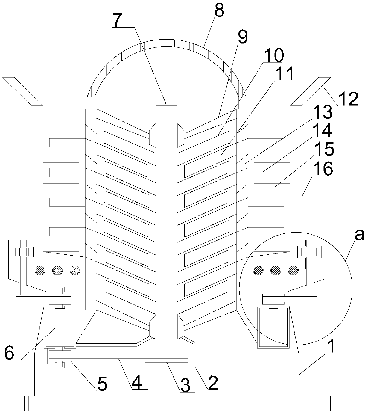
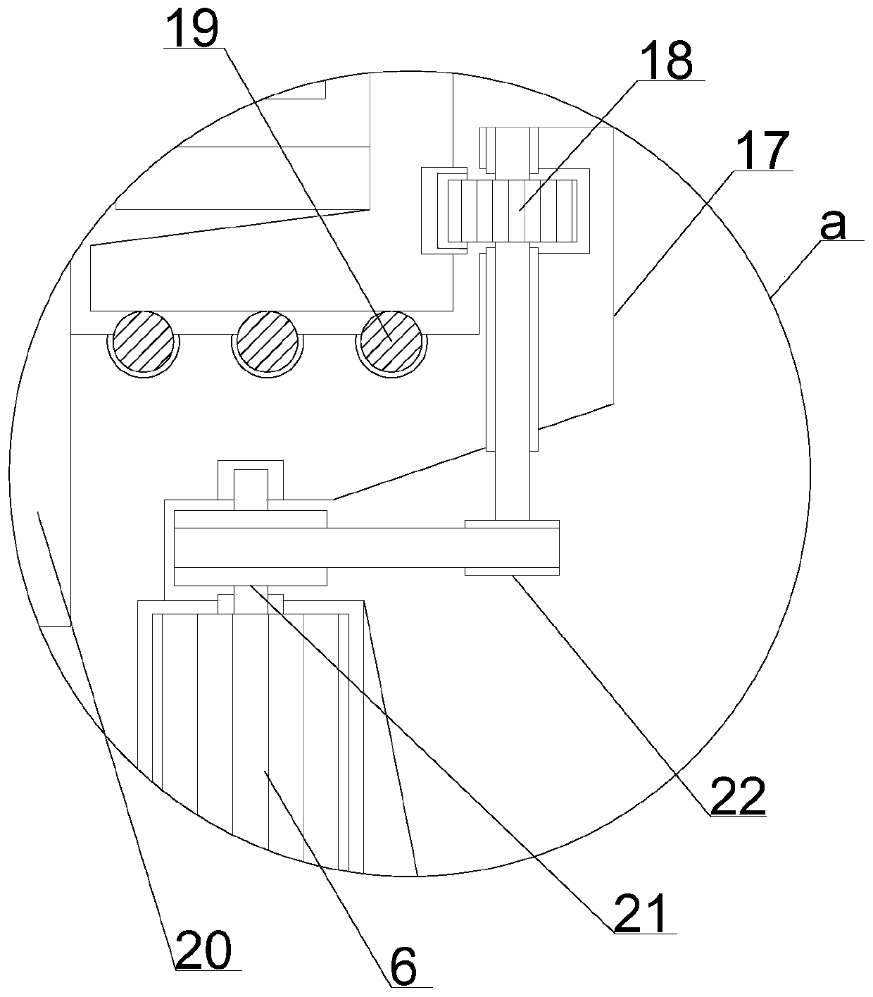
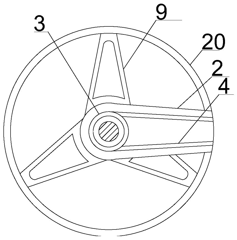
[0018] see Figure 1~3 , in an embodiment of the present invention, an ore sleeve crushing device includes a supporting installation plate 17, and a secondary crushing installation cylinder 20 is inlaid vertically upward in the middle position of the support installation plate 17, and the secondary crushing installation cylinder 20 The upper end of 20 is provided with a spherical surface diameter-limiting filter plate 8, and the lower end edge position of the ...


PUM


Abstract

The invention discloses an ore sleeve breaking device which comprises a supporting and mounting plate; a secondary breaking mounting barrel is vertically and upwards inserted into the middle of the supporting and mounting plate; four supporting and mounting columns are arranged at the edge positions of the lower end of the supporting and mounting plate at equal angles; a limiting rotation mountinggroove is formed in the upper end of the supporting and mounting plate in a manner of matching with the secondary breaking mounting barrel; a primary breaking sleeve is concentrically and verticallyarranged on the outer side of the secondary breaking mounting barrel in a manner of matching with the limiting rotation mounting groove; a plurality of supporting balls are uniformly and half insertedinto the upper end of the limiting rotation mounting groove in a manner of matching with the lower end of primary breaking sleeve; rotation breaking columns are uniformly and horizontally arranged onthe inner side of the primary breaking sleeve; and static breaking columns are arranged on the outer side of the secondary breaking mounting barrel in a manner of matching with the rotation breakingcolumns in a rotation and staggered mode. The ore sleeve breaking device has the advantages that structural design is compact and novel, transmission is simplified and stable, ore materials are brokenfully, the utilization ratio is high, the quality is good, etc.

Description

technical field [0001] The invention relates to ore processing equipment, in particular to an ore sleeve crushing device. Background technique [0002] In order to facilitate ore loading and processing, the mining industry often uses crushing devices for crushing. However, due to the extensive processing of the ore crushing devices currently used, the crushing takes a long time, the crushing quality is poor, and the waste is serious, which seriously affects the follow-up processing. . [0003] In order to solve the above problems, the present invention is proposed, which overcomes the currently used ore crushing device and the traditional ore crushing device. Because the screening and separation method adopts a one-way form, the waste of materials in the crushing process is serious and the economic benefits are low. , to solve the traditional ore crushing device, due to the use of single crushing, resulting in uneven crushing quality, resulting in low utilization rate of or...

Claims


Application Information

Patent Timeline
Patent Type & Authority Patents(China)
IPC IPC(8): B02C13/14B02C13/20B02C13/28B02C13/282B02C13/286B02C13/30B02C13/284
CPCB02C13/14B02C13/20B02C13/28B02C13/282B02C13/284B02C13/286B02C13/30B02C2013/28618
Inventor 邢济祥
Owner 崇义县鑫成矿业有限公司
Features
  • R&D
  • Intellectual Property
  • Life Sciences
  • Materials
  • Tech Scout
  • Unparalleled Data Quality
  • Higher Quality Content
  • 60% Fewer Hallucinations
Learn More