Supercharge Your Innovation With Domain-Expert AI Agents!

Grain clutch crushing and pulverizing device

A milling device and grain technology, applied in the field of agricultural tools, can solve the problems of unreasonable and unstable connection of the transmission structure, long time consumption, shaking of the mechanism operation, etc., and achieve the effect of compact and novel structure design, stable and efficient transmission, and coherent process

Inactive Publication Date: 2017-12-29
景学良
View PDF0 Cites 0 Cited by
  • Summary
  • Abstract
  • Description
  • Claims
  • Application Information

AI Technical Summary

Problems solved by technology

[0002] Grain crushing and milling is the most common processing method in grain processing. However, due to the imperfect design of the traditional grain crushing and milling device, problems such as long time-consuming, short life, and poor processing quality in the actual use process restrict its continuous development. use and development
[0003] In order to solve the above problems, the present invention is proposed, which overcomes the traditional grain crushing and milling device. Since the crushing and milling process is a separate structure, the processing flow is incoherent, and the material transfer process adopts an open structure, which causes the material to be broken during transportation. Problems such as being polluted by the outside world solve the problems of the traditional grain crushing and milling device. Due to the unreasonable and unstable connection of the transmission structure, the operation of the mechanism is shaken, which makes the rigid impact of the device components frequent and the service life is reduced. The present invention has a compact and novel structure design. , stable and efficient transmission, coherent process, high efficiency and sanitation, long life, etc.

Method used


Image

  • Grain clutch crushing and pulverizing device
  • Grain clutch crushing and pulverizing device
  • Grain clutch crushing and pulverizing device

Examples


Embodiment Construction

[0017] The following will clearly and completely describe the technical solutions in the embodiments of the present invention with reference to the accompanying drawings in the embodiments of the present invention. Obviously, the described embodiments are only some, not all, embodiments of the present invention. Based on the embodiments of the present invention, all other embodiments obtained by persons of ordinary skill in the art without making creative efforts belong to the protection scope of the present invention.

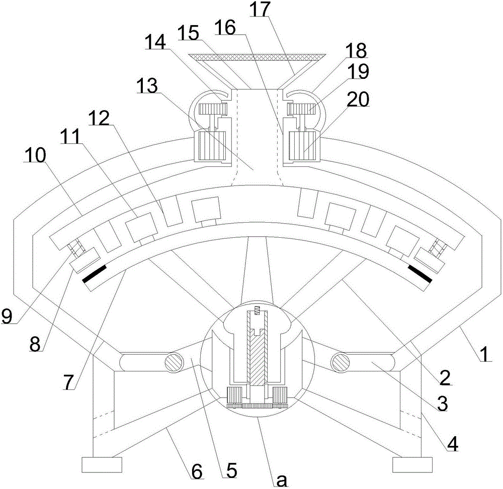
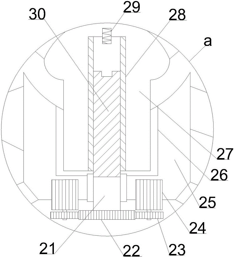
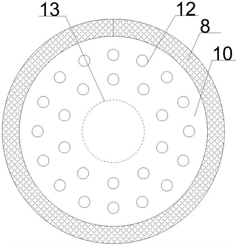
[0018] see Figure 1~3 , in an embodiment of the present invention, a grain clutch crushing and milling device includes a support mounting plate 5, the edge of the support mounting plate 5 is upwardly equipped with a working protection cover 1, and the lower side of the supporting mounting plate 5 corresponding to the working protection cover 1 Vertically be provided with support installation column 4, the lower end of described support installation column 4 i...


PUM


Abstract

The invention discloses a grain clutch crushing and milling device, which comprises a support installation plate, an operation protection cover is installed upward on the edge of the support installation plate, and a support installation column is vertically arranged on the lower side of the support installation plate corresponding to the operation protection cover. The middle position of the upper end of the operation protection cover vertically runs through the limited rotation column, and the upper end of the operation protection cover is inlaid with the limit rotation column to set the limit transmission sleeve. The lower end of the column matched with the cone-shaped blanking cylinder is vertically provided with a blanking hole, and the limit transmission sleeves on the left and right sides of the limit rotation column are symmetrically inlaid with a rotating structure. The synchronous active motor inside, and the upper end of the limit rotation column is coaxially provided with a rotating gear ring. The invention has the advantages of compact and novel structure design, stable and efficient transmission, coherent process, high efficiency and sanitation, and long service life.

Description

technical field [0001] The invention relates to an agricultural tool, in particular to a grain clutch crushing and milling device. Background technique [0002] Grain crushing and milling is the most common processing method in grain processing. However, due to the imperfect design of the traditional grain crushing and milling device, problems such as long time-consuming, short life, and poor processing quality in the actual use process restrict its continuous development. use and development. [0003] In order to solve the above problems, the present invention is proposed, which overcomes the traditional grain crushing and milling device. Since the crushing and milling process is a separate structure, the processing flow is incoherent, and the material transfer process adopts an open structure, which causes the material to be broken during transportation. Problems such as being polluted by the outside world can solve the problems of the traditional grain crushing and milli...

Claims


Application Information

Patent Timeline
Patent Type & Authority Applications(China)
IPC IPC(8): B02C9/00
CPCB02C9/00
Inventor 景学良
Owner 景学良
Features
  • R&D
  • Intellectual Property
  • Life Sciences
  • Materials
  • Tech Scout
  • Unparalleled Data Quality
  • Higher Quality Content
  • 60% Fewer Hallucinations
Learn More