
Forestry pest trapping device

A pest and forestry technology, applied in the fields of trapping or killing insects, animal husbandry, application, etc., can solve the problems of ineffective installation, unfavorable use, inconvenient addition and replacement of traps, etc.

Active Publication Date: 2021-05-11
雄安爱树科技有限公司
View PDF10 Cites 0 Cited by
  • Summary
  • Abstract
  • Description
  • Claims
  • Application Information

AI Technical Summary

Problems solved by technology

[0002] Most of the pest trapping devices in the prior art use traps to lure the pests, and then use insecticides or electric shocks or siege to kill the pests, or use the phototaxis of the pests to kill them at night. The related technologies are relatively mature; but most The trapping device does not have a good killing effect, and the use of insecticide poisoning often makes the pests resistant, which makes it impossible to use for a long time
[0003] The patent literature with the publication number CN202010878995.7 in the prior art provides a trapping device for forestry pests. While realizing the prior art, the inventors found the following problems: 1. The device has high production cost, which is not conducive to It is located in multiple sample points for reasonable use; 2. The device adopts dynamic operation, and the trapping effect is poor; 3. The fixing ability of the modified device is weak, which prevents it from being effectively and stably clamped on the tree, which makes the device unable to be installed effectively 4. The device is not convenient for collecting the captured pests reasonably, and it is not convenient for adding and replacing the traps reasonably, and the actual working effect is not good. In view of this, we Propose a trapping device for forestry pests

Method used


Image

  • Forestry pest trapping device
  • Forestry pest trapping device
  • Forestry pest trapping device

Examples


Embodiment Construction

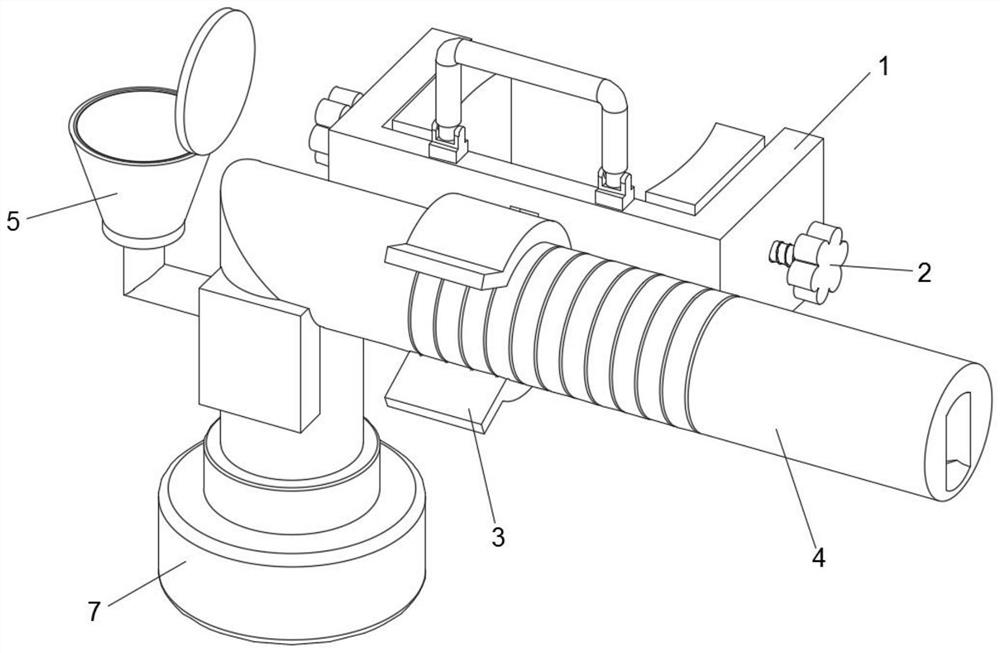
[0024] In describing the present invention, it should be understood that the terms "center", "longitudinal", "transverse", "length", "width", "thickness", "upper", "lower", "front", " Orientation indicated by rear, left, right, vertical, horizontal, top, bottom, inside, outside, clockwise, counterclockwise, etc. The positional relationship is based on the orientation or positional relationship shown in the drawings, and is only for the convenience of describing the present invention and simplifying the description, rather than indicating or implying that the referred device or element must have a specific orientation, be constructed and operated in a specific orientation, Therefore, it should not be construed as limiting the invention.

[0025] In the description of the present invention, "plurality" means two or more, unless otherwise specifically defined.

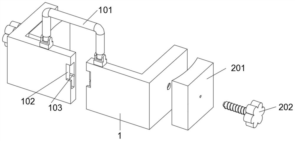
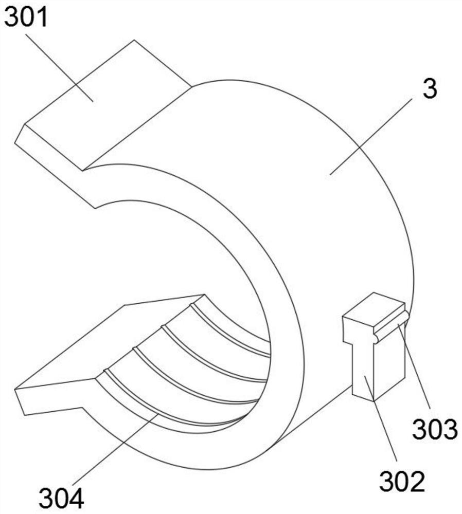
[0026] see Figure 1-4 , the present invention provides a kind of technical scheme:

[0027] A trapping device for f...


PUM


Abstract

The invention discloses a forestry pest trapping device, and belongs to the technical field of forestry engineering pest control. The forestry pest trapping device comprises a mounting base, a handle is mounted on the top surface of the mounting base, two clamping assemblies are symmetrically arranged at the left end and the right end of the mounting base, a clamping base is movably mounted at the front end of the mounting base, a trapping pipe is clamped in the clamping base, a trapping groove is formed in a transverse pipe of the trapping pipe, and a feeding assembly is rotationally connected to a vertical pipe of the trapping pipe; and a tiling assembly is arranged below the terminal of the feeding assembly, and the terminal of the vertical pipe of the trapping pipe is connected with a collecting bottle through screws. The forestry pest trapping device is installed at all positions in a garden through the mounting base, and the device can be clamped on a tree through screwing-in of the clamping assemblies; by means of the movably-installed clamping base, assembling of the device is facilitated, and the trapping pipe is conveniently installed movably; and the special labyrinth structure in the trapping pipe is utilized, so that after trapping agents are added into the feeding assembly on the trapping pipe, pests enter the trapping pipe along drifting smell, and then the trapping effect that the pests enter the trapping pipe easily and exit from the trapping pipe difficultly is achieved.

Description

technical field [0001] The invention relates to the technical field of prevention and control of forestry engineering diseases and insect pests, in particular to a forestry pest trapping device. Background technique [0002] Most of the pest trapping devices in the prior art use traps to lure the pests, and then use insecticides or electric shocks or siege to kill the pests, or use the phototaxis of the pests to kill them at night. The related technologies are relatively mature; but most The killing effect of traditional trapping devices is not good, and the use of insecticide poisoning often makes pests resistant to pesticides, resulting in the inability to use them for a long time. [0003] The patent literature with the publication number CN202010878995.7 in the prior art provides a trapping device for forestry pests. While realizing the prior art, the inventors found that it has the following problems: 1. The device has high production cost, which is not conducive to It...

Claims


Application Information

Patent Timeline
Patent Type & Authority Applications(China)
IPC IPC(8): A01M1/02
CPCA01M1/02Y02A50/30
Inventor 朱刚
Owner 雄安爱树科技有限公司
Learn More