High-temperature fused salt storage tank device

A technology of high-temperature molten salt storage tanks and shock absorbing devices, which is applied in tank trucks, packaging, transportation and packaging, etc. It can solve problems such as storage tank blockage, disrupting production continuity, and affecting normal production, so as to maintain temperature and reduce loss Effect

Inactive Publication Date: 2018-04-27
新昌县城关海顺机械厂
View PDF0 Cites 3 Cited by
  • Summary
  • Abstract
  • Description
  • Claims
  • Application Information

AI Technical Summary

Problems solved by technology

[0002] High-temperature molten salt is a molten body formed after melting salts, such as a molten body of alkali metal, alkaline earth metal halide, nitrate, and sulfate. High-temperature molten salt is solid at standard temperature and atmospheric pressure, and exists after the temperature rises. In the liquid phase, there are all kinds of storage tanks in chemical plants, but due to the particularity of high-temperature molten salt, ordinary storage tanks do not have good thermal insulation performance. After a long storage time, high-temperature molten salt will solidify and crystallize , not well suited for the storage of high-temperature molten salt, and high-temperature molten salt is easy to crystallize and precipitate solid particles, which is likely to cause blockage of the storage tank, affect the normal production, and destroy the continuity of production

Method used


Image

  • High-temperature fused salt storage tank device
  • High-temperature fused salt storage tank device

Examples


Embodiment Construction

[0018] The following will clearly and completely describe the technical solutions in the embodiments of the present invention with reference to the accompanying drawings in the embodiments of the present invention. Obviously, the described embodiments are only some, not all, embodiments of the present invention.

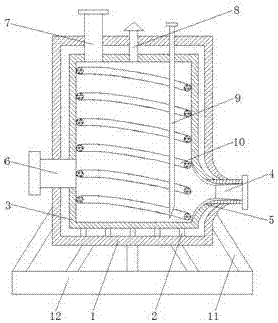
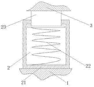
[0019] refer to Figure 1-2 , a high-temperature molten salt storage tank device, including a first shell 1, a shock absorber 2 and a second shell 3, the bottom inner wall of the first shell 1 is welded with a shock absorber 2, and the upper end of the shock absorber 2 Welded with the second shell 3, the double-layer structure of the first shell 1 and the second shell 3 can play a role of heat insulation, reducing heat loss through the surface of the storage tank, so as to better maintain the temperature of the high-temperature molten salt The lower part of the side wall of the first casing 1 is provided with a through hole, and the inner wall of the through hole is ...


PUM


Abstract

The invention discloses a high-temperature molten salt storage tank device, which comprises a first shell, a shock absorbing device and a second shell. The double-layer structure of the first shell and the second shell can play a role of heat insulation, reducing The heat is lost through the surface of the storage tank, which enhances the heat preservation effect. The lower part of the side wall of the first shell is provided with a discharge pipe, and the inner wall of the discharge pipe is welded with a deflector. The first shell and the second shell are connected with the discharge pipe. The connection of the pipe is provided with rounded corners, so that the discharge port forms a smooth and gradual channel to prevent the precipitated crystals from blocking the discharge port. A manhole is provided on the side wall of the first shell away from the discharge pipe. The first The top of the housing is installed with a feed pipe, a safety valve and a liquid level gauge in sequence. The bottom of the liquid level gauge extends to the bottom of the inner cavity of the second housing. A heating tube is set inside the second housing. An electric heating wire is arranged inside, and the heating pipes are arranged in a spiral shape from top to bottom along the inner wall of the second housing to increase the heat conduction area.

Description

technical field [0001] The invention relates to the technical field of chemical storage equipment, in particular to a high-temperature molten salt storage tank device. Background technique [0002] High-temperature molten salt is a molten body formed after melting salts, such as a molten body of alkali metal, alkaline earth metal halide, nitrate, and sulfate. High-temperature molten salt is solid at standard temperature and atmospheric pressure, and exists after the temperature rises. In the liquid phase, there are all kinds of storage tanks in chemical plants, but due to the particularity of high-temperature molten salt, ordinary storage tanks do not have good thermal insulation performance. After a long storage time, high-temperature molten salt will solidify and crystallize , is not well suited for the storage of high-temperature molten salt, and high-temperature molten salt is easy to crystallize and precipitate solid particles, which may easily cause blockage of the sto...

Claims


Application Information

Patent Timeline
Patent Type & Authority Applications(China)
IPC IPC(8): B65D88/74B65D90/02B65D90/00
CPCB65D88/744B65D90/00B65D90/02B65D90/022
Inventor 程仁怀
Owner 新昌县城关海顺机械厂
Why Eureka
Try Eureka