High-efficiency asphalt tank

An asphalt tank, high-efficiency technology, applied in the field of high-efficiency asphalt tanks, can solve the problems of low heating efficiency and achieve the effect of improving efficiency

Inactive Publication Date: 2018-04-27
CHENGDU KECHUANGCHENG TECH
View PDF3 Cites 4 Cited by
  • Summary
  • Abstract
  • Description
  • Claims
  • Application Information

AI Technical Summary

Problems solved by technology

[0006] In order to solve the problem of low heating efficiency in the existing asphalt tank, the present invention provides a high-efficiency asphalt tank, which can improve the heating efficiency of asphalt in the high-efficiency asphalt tank

Method used


Image

  • High-efficiency asphalt tank
  • High-efficiency asphalt tank
  • High-efficiency asphalt tank

Examples


Embodiment Construction

[0022] The present invention will be further described below in conjunction with the embodiments, and the described embodiments are only a part of the embodiments of the present invention, not all of them. Based on the embodiments of the present invention, other used embodiments obtained by persons of ordinary skill in the art without creative efforts all belong to the protection scope of the present invention.

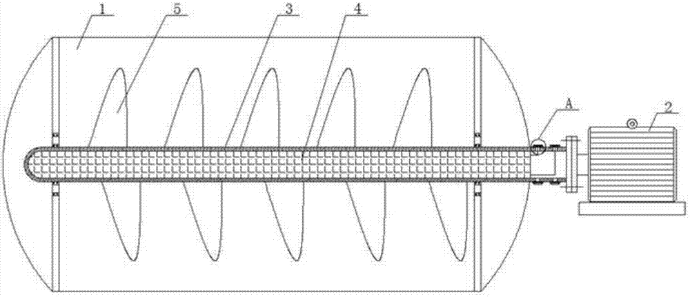
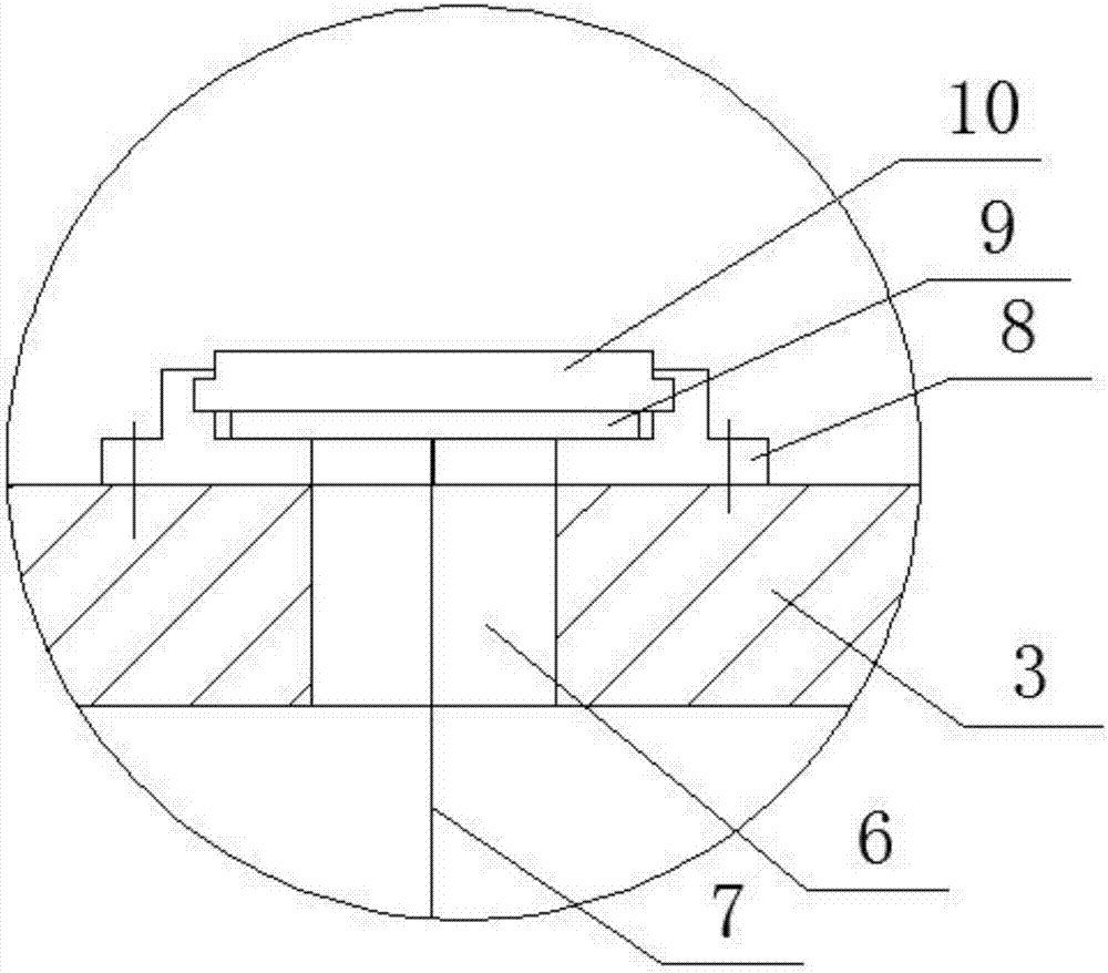
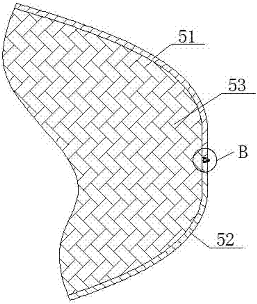
[0023] In conjunction with the accompanying drawings, the high-efficiency asphalt tank body provided by the present invention includes a tank body 1, and a drive motor 2 is arranged outside the tank body 1, and the drive motor 2 is connected to a stirring shaft, and the stirring shaft extends into the tank body 1 And be connected with agitating blade, wherein driving motor belongs to prior art, those skilled in the art can understand and understand, do not go into details here, described agitating shaft is hollow shaft 3, is provided with electric heating in described ...


PUM


Abstract

The invention belongs to the technical field of asphalt tanks, and discloses a high-efficiency asphalt tank, which is used to solve the problem of low heating efficiency in the existing asphalt tanks. The present invention comprises a tank body, a drive motor is arranged outside the tank body, the drive motor is connected with a stirring shaft, the stirring shaft extends into the tank body and is connected with a stirring blade, the stirring shaft is a hollow shaft, the An electric heating wire is arranged in the hollow shaft, the stirring blade is a hollow blade, and an electric heating wire layer electrically connected with the electric heating wire in the hollow shaft is arranged in the hollow blade.

Description

technical field [0001] The invention belongs to the technical field of asphalt tanks, in particular to a high-efficiency asphalt tank. Background technique [0002] The finished tank of the existing asphalt spreader is a single tank (only storage function), which cannot meet the current use requirements, especially the emulsified asphalt is stored for a long time or the quality of the emulsified asphalt is unstable, resulting in asphalt precipitation, and the tank is not easy to clean. To solve this problem, tanks with heating function have appeared in the prior art. For example, the utility model patent with application number 201120515422.4 discloses a tank for asphalt sprinkling and irrigation vehicles, including heating pipes arranged in the tank. An interlayer is provided, and the interlayer communicates with the flue gas outlet of the heating pipe and the chimney arranged on the outside of the tank body; a horizontal scraping bottom stirrer is also arranged inside the ...

Claims


Application Information

Patent Timeline
Patent Type & Authority Applications(China)
IPC IPC(8): E01C19/10E01C19/16
CPCE01C19/1013E01C19/16
Inventor 雍海燕
Owner CHENGDU KECHUANGCHENG TECH
Why Eureka
Try Eureka