Pressure cooking utensil

A technology of cooking utensils and pressure, applied in the field of cooking utensils and pressure cooking utensils, can solve the problems of long cooking time, sticking to the pan, health problems, etc., and achieve the effect of shortening time, increasing pressure, and speeding up

Pending Publication Date: 2021-05-25
JOYOUNG CO LTD
View PDF19 Cites 0 Cited by
  • Summary
  • Abstract
  • Description
  • Claims
  • Application Information

AI Technical Summary

Problems solved by technology

There are two problems in this pressurization method. One is that the pressure in the cooking cavity will only rise after the cooking cavity generates steam. The process from the start of cooking to the completion of the pressure boost is very long, and the cooking time is relatively long; the other is, The external heat is transferred to the ingredients through the pot wall. During the contact process between the high-temperature pot wall and the ingredients, the ingredients tend to gelatinize and adhere to the pot wall, which is the phenomenon of sticking. Add anti-stick coating, the service life of the anti-stick coating is limited, and there are certain health problems after falling off

Method used


Image

  • Pressure cooking utensil
  • Pressure cooking utensil
  • Pressure cooking utensil

Examples


Embodiment 1

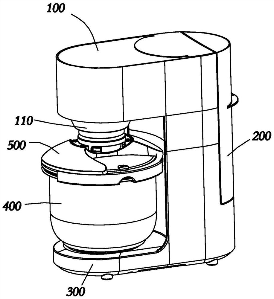
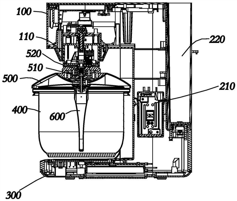
[0028] refer to Figure 1 to Figure 3 , Figure 1 to Figure 3 A first embodiment of the invention is shown.

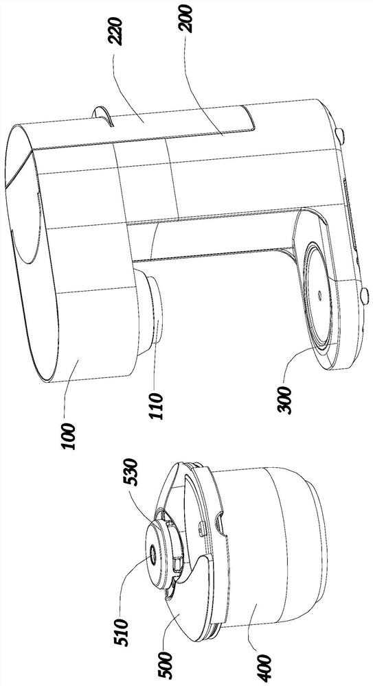
[0029] In this embodiment, the pressure cooking appliance includes a body and a pot body 400, wherein the body is composed of a body 200 and a head 100 protruding from one side of the body 200 and a base 300 and a base 300, and the body 200 is provided with The steam generating device 210 generates high-temperature and high-pressure steam through the steam generating device 210 . There is a space between the machine head 100 and the base 300 to form an open space, and the pot body 400 is placed in the open space to facilitate the putting in and taking out of the pot body 400 . In the cooking preparation stage, the pot body 400 is placed on the base 300. The pot body 400 includes the pot body 400 body and the pot cover 500. The pot cover 500 is provided with an air intake channel 510 communicating with the cooking cavity of the pot body 400. The machine head 100 is pr...

Embodiment 2

[0045] refer to Figure 4 , Figure 4 A second embodiment of the invention is shown. This embodiment is an improvement on the basis of Embodiment 1.

[0046] In this embodiment, the machine head 100 is reversibly arranged on the body 200, and the machine head 100 has a separate state from the pot body 400, and a docking state with the pot body 400. When the machine head 100 is separated from the pot body 400, the user can take off the pot body 400 from the base 300, or put the pot body 400 on the base 300; when the machine head 100 and the pot body 400 are in a docking state, the machine head The docking portion 110 on the pot cover 500 is connected to the intake channel 510 on the pot cover 500 . Compared with the solution in Embodiment 1, this embodiment uses the machine head 100 to turn over and dock with the pot body 400. When the pot body 400 is in the open state, the user can take out or put in the pot body 400 from the obliquely above, and take and place the pot body...


PUM


Abstract

The pressure cooking utensil comprises a machine body and a pot body, a steam generation device is arranged in the machine body, the pot body comprises a pot body and a pot cover, the pot cover and the pot body are buckled to form a cooking cavity, a steam guide pipe communicated with the steam generation device is arranged on the pot cover, and the steam guide pipe is communicated with the steam generation device. the steam guide pipe is provided with a steam hole for spraying steam, the steam guide pipe extends into the pressure cooking cavity to spray steam so as to quickly increase the pressure in the cooking cavity, and food materials are stirred and heated under the pressure state. According to the pressure cooking utensil, high-temperature and high-pressure steam is rapidly generated through the steam generation device in the machine body, the high-temperature and high-pressure steam is directly introduced into the cooking cavity through the steam guide pipe to achieve rapid pressurizing and heating, and the problems that an existing pressure cooking utensil is long in pressurizing time, and food materials stick to a pot are solved.

Description

technical field [0001] The invention belongs to the technical field of small kitchen appliances, and relates to a cooking appliance, in particular to a pressure cooking appliance. Background technique [0002] The advantage of high-pressure cooking compared to normal-pressure cooking is that the boiling point of water in a high-pressure environment is higher, so that cooked ingredients can be cooked quickly. Traditional pressure cooking appliances generally include two types, one is a pressure cooker heated by an open flame, and the other is an electric pressure cooker heated by electric energy. Whether it is a pressure cooker or an electric pressure cooker, the principle of pressurization is to first transfer heat to the pot wall to heat up the pot wall, and then transfer the heat to the water in the cooking cavity through the pot wall, so that the water in the cooking cavity boils to generate steam , to increase the pressure in the cooking chamber with steam. There are t...

Claims


Application Information

Patent Timeline
Patent Type & Authority Applications(China)
IPC IPC(8): A47J27/08A47J27/04A47J27/09
CPCA47J27/08A47J27/04A47J27/09A47J2027/043
Inventor 朱泽春孙正武于凌振邱雄杰王涛
Owner JOYOUNG CO LTD
Why Eureka
Try Eureka