Spraying device for photovoltaic welding strip

A technology of spraying device and photovoltaic welding strip, applied in spraying device, device for coating liquid on the surface, coating, etc., can solve the problems of non-compliance with quality requirements, high scrap rate, uneven heating, etc. Excellent, reduce the scrap rate, and solve the effect of scrap

Inactive Publication Date: 2021-11-30
ZHANGJIAGANG DONGDA IND TECH RES INST
View PDF7 Cites 0 Cited by
  • Summary
  • Abstract
  • Description
  • Claims
  • Application Information

AI Technical Summary

Problems solved by technology

[0003] The existing photovoltaic ribbon spraying device has the following technical defects: First, the traditional preheating device is in direct contact with the photovoltaic ribbon, which leads to local overheating of the photovoltaic ribbon, and uneven overall heating, and the high temperature makes the photovoltaic ribbon Deformation occurs and does not meet the quality requirements, which leads to a high scrap rate. At the same time, uneven heating causes uneven tin coating, which makes its performance low; second, the tin liquid spray is in direct contact with the photovoltaic ribbon. The amount of coating gradually decreases from the center to the outside, and at the same time, a large amount of spray diverges outward along the vertical surface of the photovoltaic ribbon through the reaction force, resulting in a waste of paint. At the same time, there is the problem of uneven coating on the surface of the photovoltaic ribbon, which will cause The performance of photovoltaic ribbon conductive electricity collection will be reduced

Method used


Image

  • Spraying device for photovoltaic welding strip
  • Spraying device for photovoltaic welding strip
  • Spraying device for photovoltaic welding strip

Examples


Embodiment

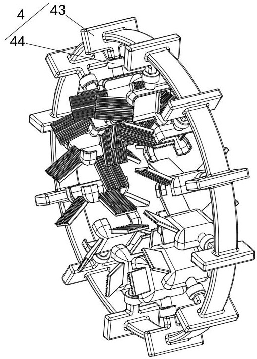
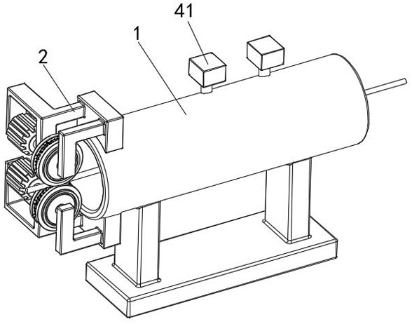
[0042] see Figure 1-8 , a spraying device for photovoltaic welding tape, including a protective shell 1, a fixing block 2, a transportation device 3, a spraying device 4 and a base, the lower side of the protective shell 1 is fixedly connected with the base, and the left part of the protective shell 1 The upper and lower sides are fixedly connected with a fixed block 2, the inner side of the fixed block 2 is fixedly installed with a transport device 3, and the inside of the protective shell 1 is fixedly installed with a spray device 4;

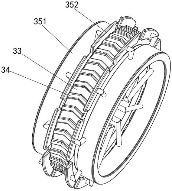
[0043] The transportation device 3 includes a first motor 31, a rotating shaft, a feeding roller 32, a rubber ring 33, a tire groove 34 and a preheating device 35. The inner front side of the fixing block 2 is fixedly connected with the first motor 31, and the rear of the first motor 31 A rotating shaft is rotatably connected to the side, a feeding roller 32 is fixedly connected to the rear side of the rotating shaft, and a rubber ring 33 is ...


PUM


Abstract

The invention discloses a spraying device for a photovoltaic welding strip. The device comprises a protective shell, a fixing block, a conveying device, a spraying device body and a base, wherein the conveying device comprises a first motor, a rotating shaft, a feeding roller, a rubber ring, a tire groove and a preheating device, the first motor is connected to the front side of the interior of the fixing block, the rotating shaft is rotationally connected to the rear side of the first motor, the feeding roller is connected to the rear side of the rotating shaft, the rubber ring is fixedly installed on the axial outer side of the feeding roller, and the preheating device is installed in the feeding roller. According to the spraying device for the photovoltaic welding strip, through the cooperation effect between the rubber ring and the tire groove, the photovoltaic welding strip is driven to be input inwards through the static friction force between the rubber ring and the photovoltaic welding strip, the purpose of automatic input is achieved, meanwhile, the rubber ring is made of rubber and has elasticity, and therefore, the effect that the shape of the photovoltaic welding strip cannot be changed due to clamping force is achieved, and the problem that the photovoltaic welding strip is scrapped due to external force factors is solved.

Description

technical field [0001] The invention relates to the technical field of photovoltaic welding strips, in particular to a spraying device for photovoltaic welding strips. Background technique [0002] Photovoltaic welding tape is mainly used for the connection between photovoltaic modules and cells, and the photovoltaic welding tape needs to be coated with a layer of tin on the outside during the production process, so as to achieve the important role of conduction and electricity collection efficiently, so it is used for photovoltaic welding tape. The tin-coated device plays a crucial role in the quality of the photovoltaic ribbon. [0003] The existing photovoltaic welding strip spraying device has the following technical defects: First, the traditional preheating device is in direct contact with the photovoltaic welding strip, thereby causing the photovoltaic welding strip to be overheated locally, and the overall heating is uneven, and the high temperature makes the photovo...

Claims


Application Information

Patent Timeline
Patent Type & Authority Applications(China)
IPC IPC(8): B05B16/20B05B13/02B05B12/18B05D3/04
Inventor 黄飞娅
Owner ZHANGJIAGANG DONGDA IND TECH RES INST
Why Eureka
Try Eureka