
Counter for water meter

A technology of counters and water meters, applied in instruments, volume meters, measuring devices, etc., can solve problems such as loss of water companies, inaccurate counting, and excessive payment of water bills by users, so as to reduce the probability of damage, ensure accuracy, and read handy effect

Pending Publication Date: 2018-04-27
宁波艾玛特仪表科技有限公司
View PDF6 Cites 0 Cited by
  • Summary
  • Abstract
  • Description
  • Claims
  • Application Information

AI Technical Summary

Problems solved by technology

However, because the existing movement is immersed in water, the photoelectric sampler is in an environment with high humidity, and the photoelectric sampler does not have good waterproof and moisture-proof capabilities, so it is easy to be damaged, especially Once the PCBA board in the photoelectric sampler gets wet, the count will be inaccurate. When the count is large, the user will pay more water bills. When the count is small, the water company will suffer losses, which may cause many problems.
Therefore, the existing integrated smart water meter has the problem that the structure of the counter and the photoelectric sampler is interdependent and cannot be separated. Afterwards, a new movement needs to be directly replaced, resulting in a short service life of the movement and the counter, so there is an urgent need for a counter that can be separated from the structure of the photoelectric sampler, and at the same time, the counter can cooperate with the photoelectric sampler for sampling

Method used


Image

  • Counter for water meter
  • Counter for water meter
  • Counter for water meter

Examples


Embodiment Construction

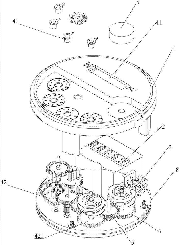
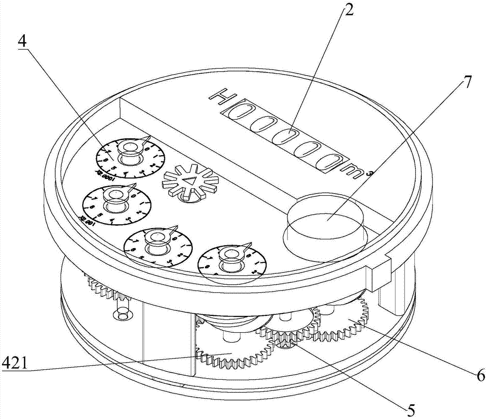
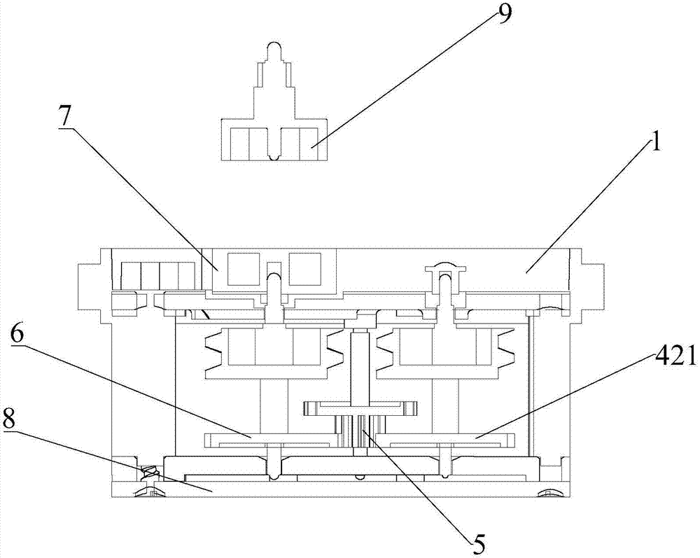
[0020] Such as Figures 1 to 7 As shown, a counter of a water meter includes an upper casing 1 and a lower casing 8, and the upper casing 1 is respectively provided with a display groove 11 and a plurality of indicating gear plates 4; the lower casing 8 is provided with a plurality of characters The roulette 2 and a cross toothed wheel 3, the character roulette includes 5 pieces, which respectively correspond to the values ​​in the ones, tens, hundreds, thousands and ten thousand digits in the decimal system one by one from right to left, and multiple character wheels The disk 2 is arranged on the output shaft of the cross-cone wheel 3 in turn and the upper end of the dial wheel 2 is accommodated in the display groove 11, and the numerical value of 0-9 is set on the dial wheel; each indicating gear disk 4 includes a pointer 41, The driving gear 42 and the scale value of 0-9 arranged on the upper housing, the scale value is circular and clockwise respectively, one end of the dr...


PUM


Abstract

The invention discloses a counter for a water meter. The counter comprises an upper shell body and a lower shell body. A displaying groove is formed in the upper shell body and a plurality of indicating gear wheels are arranged on the upper shell body; each indicating gear wheel comprises an indicator and a driving gear; values on the indicating gear wheels respectively correspond to one-ten thousandth, one-thousandth, one-hundredth, and one-tenth in a decimal system; a transition gear which meshes with any of the driving gears corresponding to the one-ten thousandth, the one-thousandth, the one-hundredth, and the one-tenth and a synchromesh gear with the same number of teeth of the driving gear are arranged outside the driving gear, an output shaft of the synchromesh gear is provided withan output magnetic cylinder, and the output magnetic cylinder is located on the upper shell body. According to the counter for the water meter, by arranging the synchromesh gear synchronized with thedriving gear, counting process of the driving gear is synchronously transmitted to the output magnetic cylinder, an intelligent water meter is formed only by arranging a photoelectric sampler outsidethe water meter while sampling is achieved, separation of structures of the photoelectric sampler and the counter is achieved, so that service life is prolonged.

Description

technical field [0001] The invention relates to the technical field of water meters, in particular to a counter of a water meter. Background technique [0002] An existing intelligent water meter includes a counter and a photoelectric sampler arranged in the movement. The counter includes a plurality of word roulettes, and the photoelectric sampler includes a plurality of PCBA boards provided with infrared photoelectric cells and control chips. Two PCBA boards are respectively arranged on both sides of the word wheel, one PCBA board is used to transmit optical signals, and the other PCBA board is used to receive optical signals. There are grooves for the light to pass through on the character wheel. When the character wheel rotates, the light signal has two possibilities: penetration and blocking. According to the position of the character wheel, a group of codes are formed correspondingly. The chip translates the code into decimal data to count. That is to say, the existi...

Claims


Application Information

Patent Timeline
IPC IPC(8): G01F15/06G01F15/075
CPCG01F15/068G01F15/075
Inventor 李雷波祝光冬林行东龚赛疆
Owner 宁波艾玛特仪表科技有限公司
Learn More