An array antenna and an antenna isolation component

An array antenna and resonant ring technology, applied in the field of communication, can solve problems such as side lobe level increase, beam deviation, and lack, and achieve the effects of less cross-polarization components, cross-polarization suppression, and strong suppression

Active Publication Date: 2021-03-19
TONGYU COMM INC
View PDF8 Cites 0 Cited by
  • Summary
  • Abstract
  • Description
  • Claims
  • Application Information

AI Technical Summary

Problems solved by technology

With the development of base station antennas towards miniaturization and light weight, at the same time, wireless communication proposes higher performance indicators such as high gain, broadband / multi-frequency, multi-beam, low sidelobe, high isolation, high and low frequency, and even different polarization The array of directions is nested and installed in the narrow internal space of the antenna. Traditional isolation methods, such as isolation bars, metal partitions, and parasitic units, cannot be installed because of insufficient space, or cannot be implemented because the parasitic effect is too significant.
In principle, conventional isolation methods use the scattering or resonance of electromagnetic waves at metal plates, metal strips or slits to weaken the incident field, thereby reducing near-field coupling. Although there is isolation effect, it is inevitable to generate new polarization. component, causing poor cross-polarization; and when the metal partition or spacer is too close to the array element, it will cause a large parasitic inductance or parasitic capacitance, which will seriously affect the impedance matching
For array antennas with small spacing (spacing less than half of the center wavelength), the lack of effective isolation will inevitably lead to serious deterioration of performance indicators, such as: cross polarization, side lobe level increase, gain drop, beam deviation, direction Figure 1 Consistency variation etc.

Method used


Image

  • An array antenna and an antenna isolation component
  • An array antenna and an antenna isolation component
  • An array antenna and an antenna isolation component

Examples


Embodiment Construction

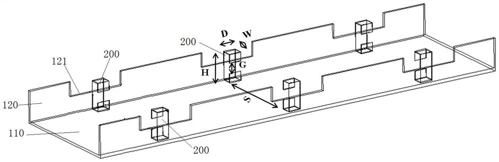
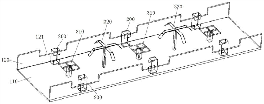
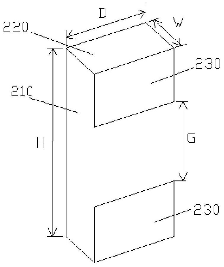
[0023] See figure 1 with figure 2 The array antenna embodiment of the present invention and the C-shaped resonant ring are mounted on the reflector, the array antenna including reflecting plate 110, provided in high frequency resonant unit 310, low frequency resonant unit 320, and C-shaped resonance ring on reflective plate 110. 200, in the present embodiment, the C-shaped resonant ring 200 is placed on the outer side of the high-frequency resonant unit 310, and the openings of the pair of C-shaped resonant ring 200 are placed toward the face-to-face surface. The specific location of the C-shaped resonant ring 200 can be adjusted according to the internal space of the antenna.

[0024] In the present embodiment, the high-frequency resonant unit 310 is a high frequency vibrator, and the low-frequency resonant unit 320 is a low frequency vibrator, such as figure 2 Indicated. The C-shaped resonant ring 200 is applied to high frequency vibrator 310 and a low frequency vibrator 320 ...


PUM


Abstract

The invention provides an array antenna. The array antenna comprises a reflection plate and a high-frequency resonant unit, a low-frequency resonant unit and C-shaped resonant rings which are arrangedon the reflection plate, wherein the C-shaped resonant rings are arranged at an outer side of the high-frequency resonant ring relative to an axis in a paired way, and openings of the C-shaped resonant rings in the paired way face to each other. The C-shaped resonant rings combined and used in the paired way are used as hidden isolation strips of the array antenna, so that the problem that a conventional isolation means cannot be implemented due to limited internal space is solved, the array element installation space is not occupied, a relatively high isolation effect also can be achieved, and a relatively high suppression effect on cross polarization is achieved. The C-shaped resonant ring hidden isolation strips are electromagnetically coupled between the resonant rings, so that an electromagnetic field among array elements is limited between the C-shaped resonant rings, a propagation passage of the electromagnetic field is changed, the coupling among the array elements is reducedor eliminated; and moreover, since the scattering cross section of each resonant ring is small, the generated cross polarization is far lower that of the conventional means.

Description

[Technical field] [0001] The present invention relates to the field of communications, and more particularly to a contact isolation assembly composed of a paired resonant ring, and an array antenna using the contact isolation strip to improve the isolation effect. 【Background technique】 [0002] The antenna as a key front part of the wireless communication system, and the performance of its performance is determined to the operator's network quality. In recent years, with the rapid growth of mobile users, the communication system is constantly updating and expanding, and the design of the antenna is increasingly demanding. As the base station antennas are small, lightweight development, while wireless communication proposes high performance indicators, high-frequency, high-frequency, multi-beam, low sub-petals, high isolation, etc., high and low frequency, or even different polarization The direction of the array is nested in the interior space of a narrow antenna, a conventional...

Claims


Application Information

Patent Timeline
Patent Type & Authority Patents(China)
IPC IPC(8): H01Q1/52H01Q1/38H01Q15/14H01Q21/10
CPCH01Q1/38H01Q1/52H01Q15/14H01Q21/10
Inventor 丁文吴中林
Owner TONGYU COMM INC
Why Eureka
Try Eureka