Electronic image system for instantly taking and displaying image
An electronic image and video technology, applied in the direction of closed-circuit television system, television system components, television, etc., can solve the problems of increased cost, unsuitable application, inability to achieve backward features, etc., and achieve the effect of easy setup and easy popularization.
- Summary
- Abstract
- Description
- Claims
- Application Information
AI Technical Summary
Problems solved by technology
Method used
Image

Examples
Embodiment Construction
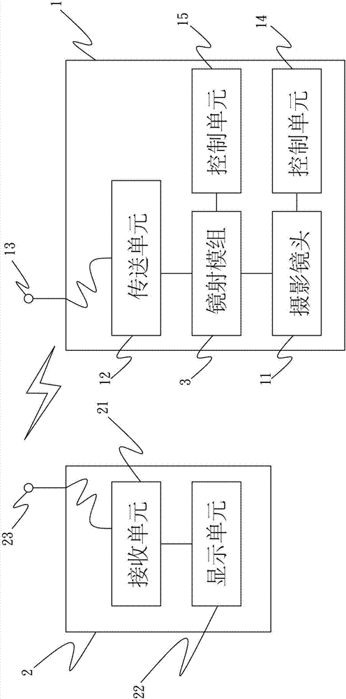
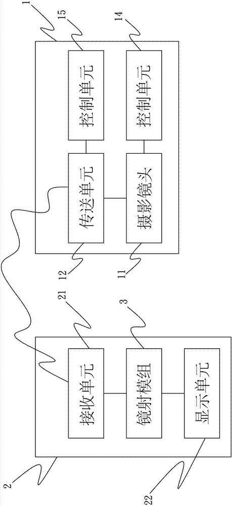
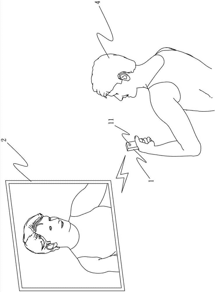
[0061] see figure 1 , figure 2 The electronic image system for capturing and displaying images in real time in the present invention mainly includes a controller 1 , a display device 2 and a left and right mirror module 3 .
[0062] The controller 1 has a photographic lens 11 and a transmission unit 12. The photographic lens 11 is used to capture image signals, and after the capture is completed, the captured image signals are transmitted through the transmission unit 12 immediately.
[0063] The display device 2 has a receiving unit 21 and a display unit 22 , the receiving unit 21 receives the signal transmitted from the transmitting unit 12 of the controller 1 , and displays the received image on the display unit 22 in real time.
[0064] The left-right mirroring module 3 is used for left-right mirroring of the video signal captured by the photographing lens 11 and then displaying it on the display device 2 .
[0065] Such as figure 1 As shown, the transmitting unit 12 a...
PUM
 Abstract
Description
Claims
Application Information
 - Generate Ideas
- Intellectual Property
- Life Sciences
- Materials
- Tech Scout
- Unparalleled Data Quality
- Higher Quality Content
- 60% Fewer Hallucinations
Browse by: Latest US Patents, China's latest patents, Technical Efficacy Thesaurus, Application Domain, Technology Topic, Popular Technical Reports.
© 2025 PatSnap. All rights reserved.Legal|Privacy policy|Modern Slavery Act Transparency Statement|Sitemap|About US| Contact US: help@patsnap.com