Heat dissipation device

A heat dissipation device and heat sink technology, which is applied in identification devices, cooling/ventilation/heating transformation, instruments, etc., can solve problems such as uneven heat dissipation, chip performance degradation, and chips that cannot quickly dissipate heat, and achieve the effect of improving heat dissipation efficiency

Pending Publication Date: 2018-04-27
SHENZHEN DICOLOR OPTOELECTRONICS
View PDF0 Cites 6 Cited by
  • Summary
  • Abstract
  • Description
  • Claims
  • Application Information

AI Technical Summary

Problems solved by technology

[0003] Due to the different chips on the PCB, the working temperature is different. If a uniformly adapted heat sink is used, the chip with a higher temperature will not be able to dissipate heat quickly, and the heat dissipation will be uneven, resulting in a decrease in chip performance.

Method used


Image

  • Heat dissipation device
  • Heat dissipation device
  • Heat dissipation device

Examples


Embodiment Construction

[0019] The technical solutions of the present invention will be further described below in conjunction with the accompanying drawings and through specific implementation methods.

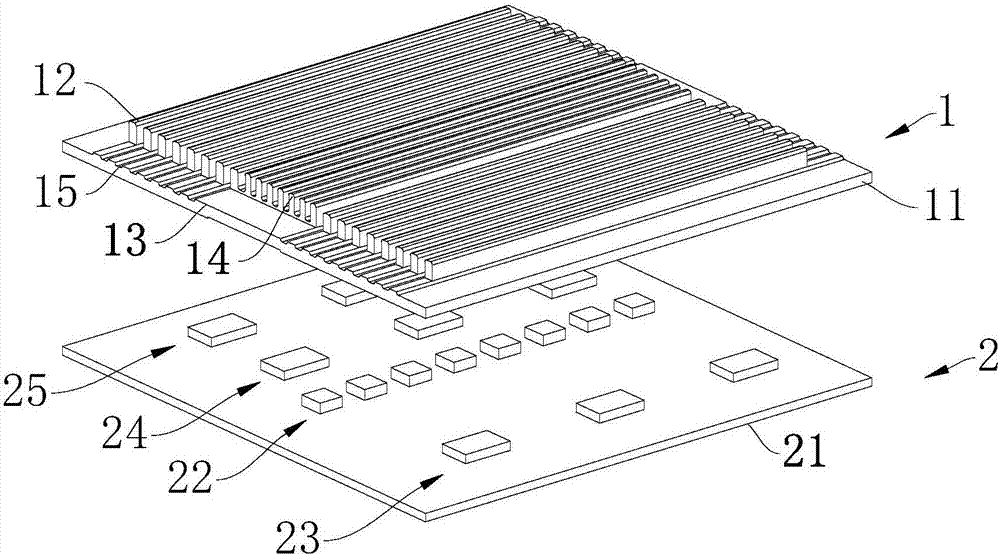
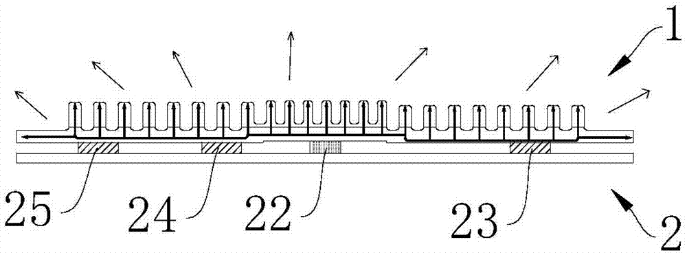
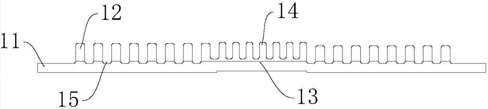
[0020] combine Figure 1 to Figure 4 As shown, a heat dissipation device in this embodiment includes a heat dissipation assembly 1 and a circuit board 2 matched with the heat dissipation assembly 1. The heat dissipation assembly 1 includes a heat conduction plate 11 and a plurality of first Heat sinks 12 are arranged in parallel and spaced between adjacent first heat sinks 12; the circuit board 2 includes a substrate 21, and a plurality of chip units arranged on the upper surface of the substrate 21, and the lower surface of the heat conducting plate 11 is closely attached to the plurality of chip units of the upper surface.

[0021] Specifically, combine figure 1 , image 3 and Figure 4 As shown, the middle part of the heat conducting plate 11 is provided with a planar protrusion 13 , and the ...


PUM


Abstract

The invention discloses a heat dissipation device, comprising a heat dissipation assembly and a circuit board matched with the heat dissipation assembly, the heat dissipation assembly includes a heat conduction plate, and a plurality of first heat dissipation fins detachably connected to the heat conduction plate, The adjacent first heat sinks are arranged in parallel and at intervals; the circuit board includes a substrate, and a plurality of chip units arranged on the upper surface of the substrate, and the lower bottom surface of the heat conducting plate is closely attached to the plurality of chips the top surface of the unit. The heat dissipation device designed with this structure can flexibly adjust the number of first heat sinks according to the heating temperature of different chip units on the bottom surface of the heat conduction plate because the first heat sink is engaged with the heat conduction plate, thereby effectively improving the heat dissipation component. cooling efficiency.

Description

technical field [0001] The invention relates to the technical field of LED display screens, in particular to a heat dissipation device. Background technique [0002] With the vigorous development of high technology, electronic products are becoming more and more intelligent and complex, the volume of electronic components tends to be miniaturized, and the density per unit area is also getting higher and higher. The direct impact of this situation is that electronic products generate more and more heat during operation. If there is no good heat dissipation method to remove the heat generated by the electrons, these excessively high temperatures will lead to electron ionization and thermal stress in the electronic components, resulting in a decrease in overall stability and shortening the life of the electronic components themselves. Therefore, how to remove these heats to avoid overheating of electronic components has always been a problem that cannot be ignored. [0003] D...

Claims


Application Information

Patent Timeline
Patent Type & Authority Applications(China)
IPC IPC(8): H05K7/20G09F9/33
CPCH05K7/20963G09F9/33
Inventor 吴明金王周坤徐陈爱王群罢
Owner SHENZHEN DICOLOR OPTOELECTRONICS
Why Eureka
Try Eureka