No-load energy-saving device for electric welding machine

An energy-saving device and electric welding machine technology, which is applied in arc welding equipment, welding equipment, welding accessories, etc., can solve the problems of high failure rate, high manufacturing cost, inconvenient operation, etc., achieve reliable no-load energy saving, improve life, and reduce arc The effect of loss

Pending Publication Date: 2018-05-01
河南省黄河防爆起重机有限公司
View PDF9 Cites 1 Cited by
  • Summary
  • Abstract
  • Description
  • Claims
  • Application Information

AI Technical Summary

Problems solved by technology

The application number is 200620024163.4. The energy-saving device of the electric welding machine disclosed in the Chinese patent document, through connecting the AC contactor in series on the transformer coil of the electric welding machine, connecting the current transformer and the bistable trigger circuit on the electric welding handle to achieve the control of the electric welding machine at no load The purpose of automatic power-off in time, but its circuit structure is complex, the number of components used is large, there are problems of high manufacturing cost and high failure rate
The energy-saving electric welding machine disclosed in the Chinese patent document with the application number 200820118834.2 directly controls the action of the contactor by setting a button switch on the electric welding handle, so as to achieve the purpose of real-time control of the power supply of the electric welding machine. The problem of inconvenience is that the welder must always press the button switch to keep the contactor in working condition during the welding operation, and the machine will be turned off when he releases his hand. Moreover, when the operation needs to be suspended for a short time during the welding rod replacement, joint processing, workpiece position adjustment, etc., repeated restart Starting the welding machine will cause high current impact damage to the welding machine, and the starting process will consume more energy

Method used


Image

  • No-load energy-saving device for electric welding machine
  • No-load energy-saving device for electric welding machine

Examples


Embodiment Construction

[0011] Hereinafter, the present invention will be described in detail with reference to the drawings and examples. It should be noted that, in the case of no conflict, the embodiments of the present invention and the features in the embodiments can be combined with each other.

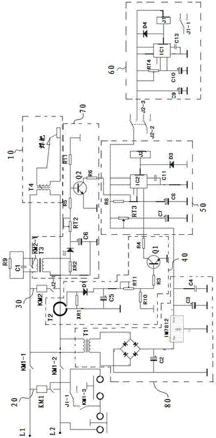
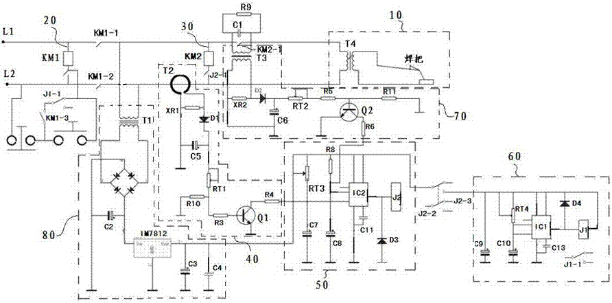
[0012] Such as figure 1 In one embodiment of the no-load energy-saving device for an electric welding machine shown in the present invention, the no-load energy-saving device for an electric welding machine includes that the primary coil of the transformer T4 of the electric welding machine 10 is connected to the power terminals L1 and L2, and the two power terminals L1 , L2 is also connected with the first control branch 20 composed of the pull-in coil of the first contactor KM1 and the normally closed contact J1-1 of the first relay J1, and the first control branch is also connected in parallel with a free The load energy-saving control branch 30, the no-load energy-saving control branch 30 includes...


PUM


Abstract

The invention relates to a no-load energy-saving device for an electric welding machine. A primary coil of a transformer of the energy-saving device is connected with power supply terminals, and a first control branched circuit and a no-load energy-saving control branched circuit are further connected between the two power supply terminals; the no-load energy-saving control branched circuit comprises an attraction coil of a second contactor and a normally-closed contact of a second relay; and a current detection module for detecting the working state of the energy-saving device is further arranged between a normally-open contact of a first contactor and the no-load energy-saving control branched circuit and is further connected with a no-load delaying module, and the no-load delaying module is connected with an energy-saving delaying module through a normally-open contact of the second contactor. According to the no-load energy-saving device, the magnitude of a working current of the electric welding machine can be detected by virtue of a mutual inductor of the current detection module, and the working state of the energy-saving device can be judged; and by utilizing a delaying chip in the no-load delaying module, the second relay can be electrified and attracted after the electric welding machine enters a no-load state for a preset period of time, and the electric welding machine can enter an energy-saving mode, so that the no-load and energy-saving effects of the electric welding machine can be reliably realized.

Description

technical field [0001] The invention relates to an energy-saving control technology of an electric welding machine, in particular to a no-load energy-saving device for an electric welding machine. Background technique [0002] The electric welding machine is a kind of intermittent working equipment with large power consumption. The load and no-load are carried out alternately. The electric welding machine still consumes a lot of power when it is unloaded. 10%~20%, there are many kinds of energy-saving devices for electric welding machines at present. The application number is 200620024163.4. The energy-saving device of the electric welding machine disclosed in the Chinese patent document, through connecting the AC contactor in series on the transformer coil of the electric welding machine, connecting the current transformer and the bistable trigger circuit on the electric welding handle to achieve the control of the electric welding machine at no load The purpose of automat...

Claims


Application Information

Patent Timeline
Patent Type & Authority Applications(China)
IPC IPC(8): B23K9/10B23K9/32
CPCB23K9/105B23K9/32
Inventor 贺成亮邓东军胡林中胡鸣超余超明
Owner 河南省黄河防爆起重机有限公司
Why Eureka
Try Eureka