

USB multi-functional LED clip lamp
a multi-functional, led clip technology, applied in the direction of lighting and heating apparatus, lighting support devices, coupling device connections, etc., can solve the problems of frequent replacement, short life of energy-saving bulbs, incandescent bulbs not saving energy, etc., and achieve the effect of simple structur
- Summary
- Abstract
- Description
- Claims
- Application Information
AI Technical Summary
Benefits of technology
Problems solved by technology
Method used
Image

Examples
embodiment 1
Preferred Embodiment 1
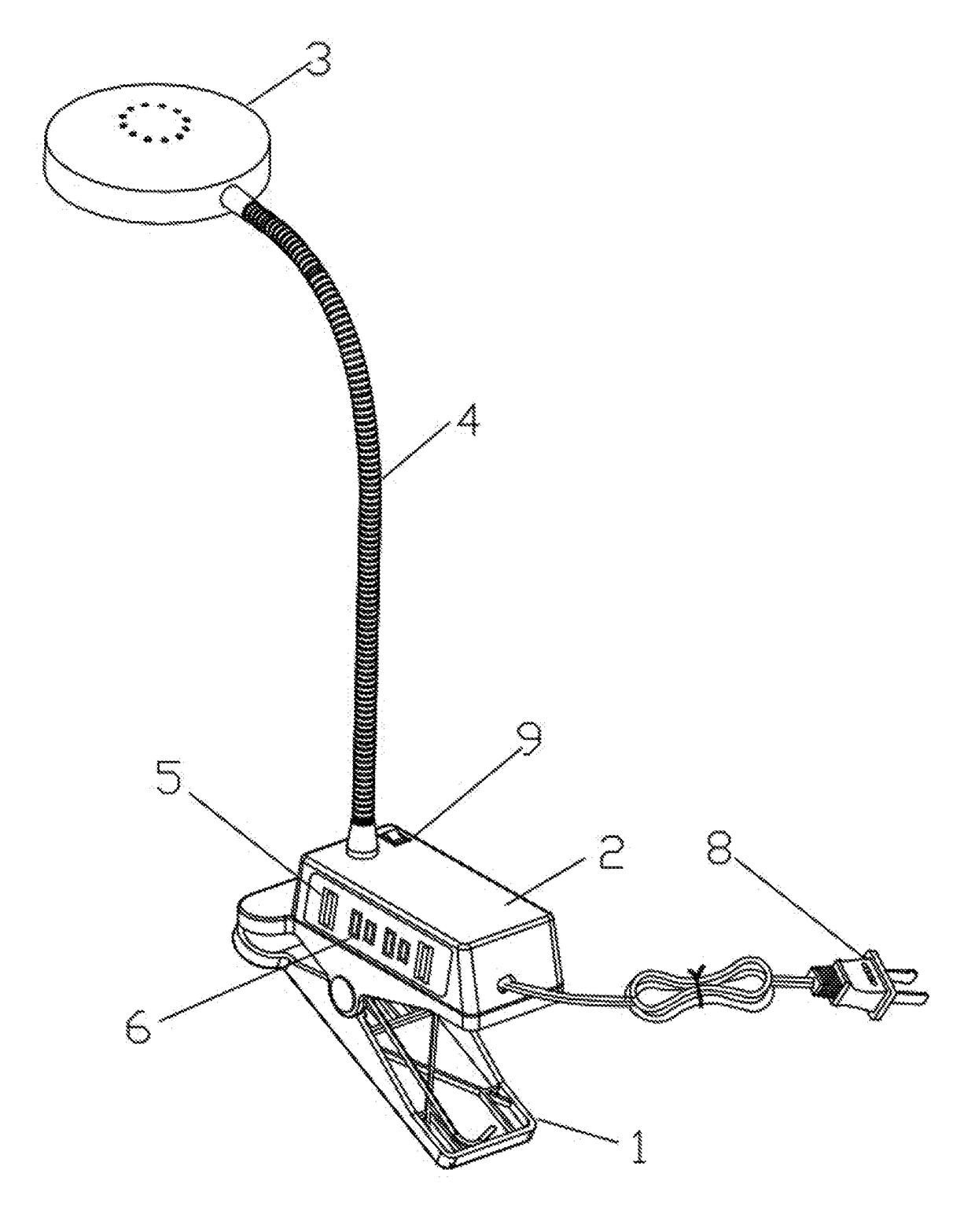
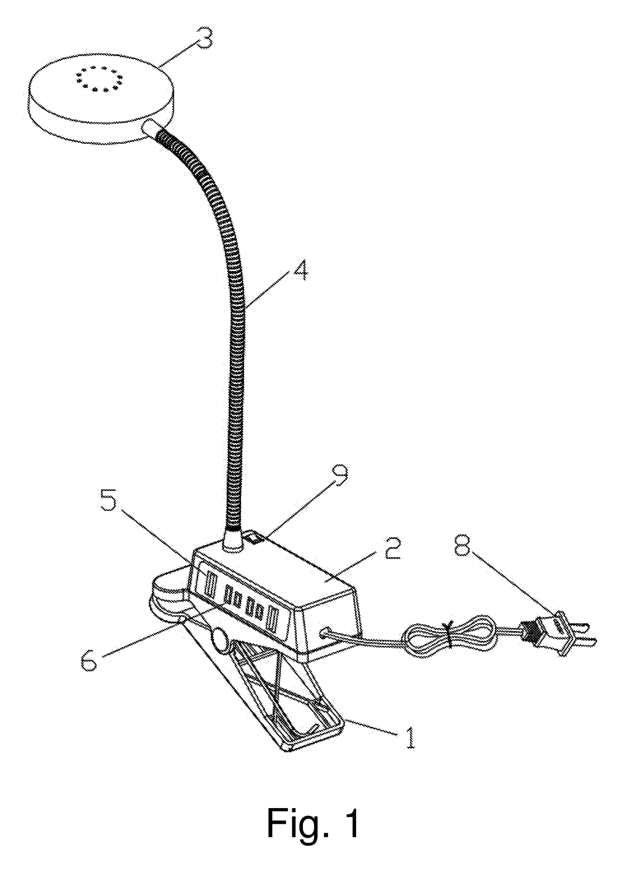
[0033]Referring to FIGS. 1 and 2 of the drawings, A USB (universal serial bus) multi-functional LED (light emitting diode) clip lamp according to the preferred embodiment 1 comprises: a lightshade 3, an LED light source 14, a supporting column and a holder, wherein the LED light source 14 is mounted inside the lightshade 3, and the supporting column has a rotatable structure. According to the preferred embodiment 1, the supporting column is formed by a soft tube 4 which is free to bend or rotate, wherein a top end of the soft tube 4 is connected to the lightshade 3, and a bottom end of the soft tube 4 is mounted on the base, in such a manner that the LED light source 14 is adjustable by rotating the soft tube 4.
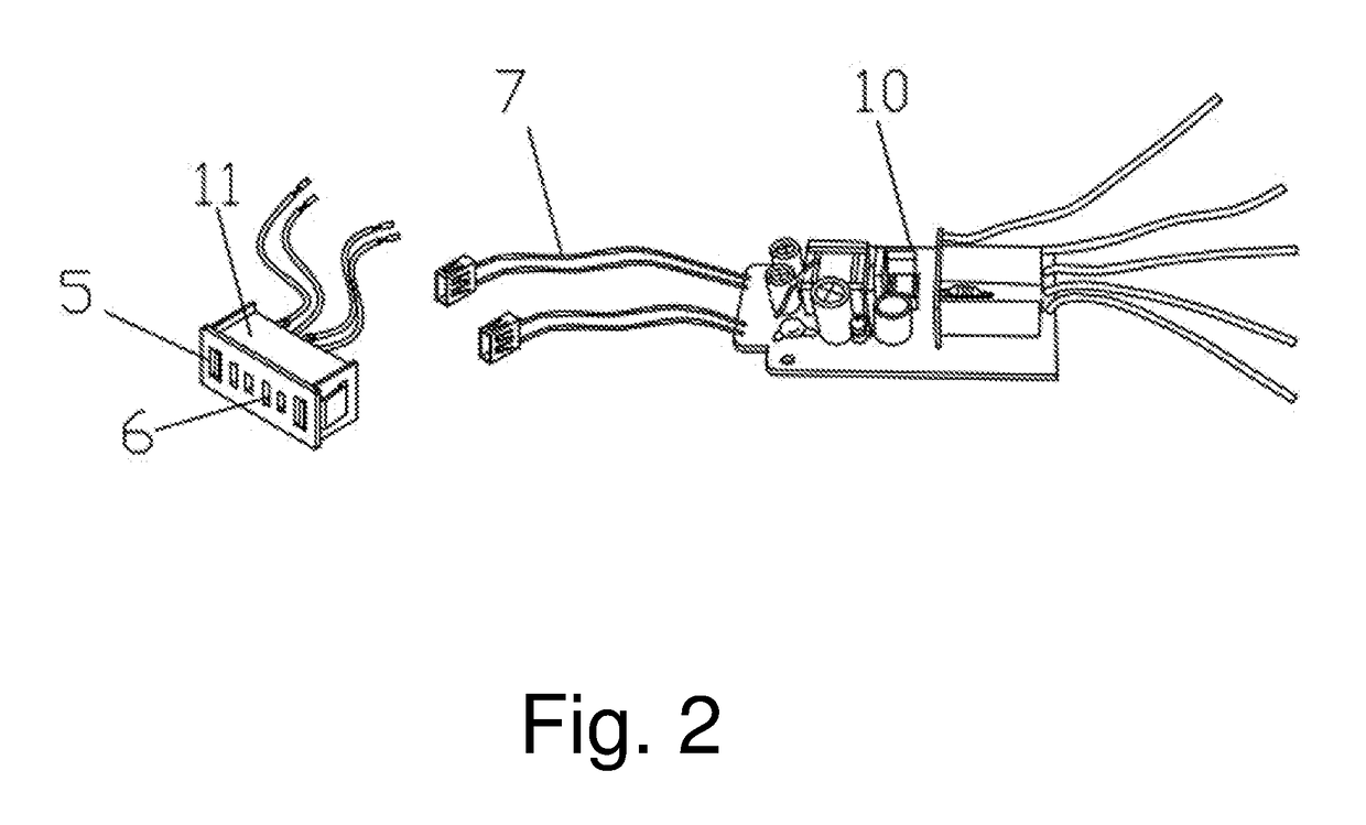
[0034]A power plug 8 is connected to the base for supplying the LED light source 14; wherein: the base comprises a clip 1 for clamping and a connecting box 2 at a top of the clip 1, wherein a main control circuit board 10 is arranged inside the connectin...
embodiment 2
Preferred Embodiment 2
[0035]According to the preferred embodiment 2 and referring to FIGS. 3 and 4, different from the preferred embodiment 1, the LED driving module is arranged inside the power plug 8, for decreasing a volume of the connecting box 2. Referring to the drawings, when LED driving module is arranged inside the power plug 8, the power socket 6 is not able to directly output a high voltage. Therefore, for outputting the high voltage through the power socket 6, the LED driving module needs to be placed inside the connecting box 2 for outputting both the high voltage and a low voltage. Meanwhile, a linear touching light adjuster 12 is used for freely adjusting light by touching. In addition, according to the preferred embodiment 2, the USB interface 5 and the power socket 6 are both provided at a top face of the connecting box 2. A cover 13 is provided at a bottom of the connecting box 2, the lightshade 3 has a detachable structure, and a front end of the lightshade 3 comp...
embodiment 3
Preferred Embodiment 3
[0036]According to the preferred embodiment 3 and referring to FIGS. 5 and 6, different from the preferred embodiment 1, the supporting column comprises a holder 19 and a movable column 18, wherein the holder 19 is mounted on a top face of the connecting box 2, a bottom portion of the movable column 18 is mounted on the holder 19 through screws, a top portion of the movable column 18 is connected to the lightshade 3 through a movable joint which is rotatable in all directions, and a rotation shaft is arranged at a middle portion of the movable column 18. According to the preferred embodiment 3, the USB interface 5 and the power socket 6 are both provided at a top face of the connecting box 2. A cover 13 is provided at a bottom of the connecting box 2, the lightshade 3 has a detachable structure, and the LED light source 14 comprises a lens 7 and a cooling fin 16.
[0037]One skilled in the art will understand that the embodiment of the present invention as shown i...
PUM
 Abstract
Description
Claims
Application Information