Door-opening warning system of car
An alarm system and vehicle technology, applied in the field of vehicles, can solve problems such as low resolution, poor directionality and limitation of ultrasonic waves, and achieve the effects of high detection range accuracy, improved response speed, and improved intelligence
Inactive Publication Date: 2018-05-01
CONTINENTAL HOLDING CHINA CO LTD
9 Cites 6 Cited by
AI-Extracted Technical Summary
Problems solved by technology
[0005] 1. Ultrasound has poor directionality, large divergence angle, and low resolution. It is easy to use the car in the adjacent lane as the detection object, resulting in a wrong reminder
[0006] 2. The response speed of ultrasonic waves is not fast enough, and the propagation speed of ultrasonic waves is the speed of sound
If the target distance is measured for fast-moving objects such as battery cars and motorcycles, the lag is large, and the reminder may not be issued in time
[0007] 3. The attenuation of ultrasonic waves is relativ...
Method used
Embodiments of the present invention display the pattern of the moving object approaching the vehicle and the distance and speed information of the moving object on the windshield glass or the door glass by using the vehicle-mounted head-up display system. The pattern of the moving object approaching the vehicle can be, for example, The moving object shown in animation is constantly approaching the vehicle, which can remind the occupants of the vehicle more conspicuously, so as to effectively avoid the risk of collision. Figure 4A schematically shows the pattern of a moving object approaching the vehicle displayed on the front windshield of the vehicle and the distance and speed information of the moving object; Figure 4B schematically shows the movement displayed on the door glass of the vehicle Patterns of objects approaching the vehicle as well as distance and speed information for moving objects.
Embodiments of the present invention have adopted millimeter-wave radar to carry out the detection of moving object around the vehicle, therefore have detection distance, high detection precision and accuracy, fast reflection speed, not affected by weather and night and able to move Object recognition and other advantages.
[0052] By outputting the virtual scene v...
Abstract
The invention provides a door-opening warning system of a car. The method comprises a car-mounted millimeter-wave radar and a control module. The car-mounted millimeter-wave radar is configured to emit a millimeter-wave signal around the car and receive and process the millimeter-wave signal reflected by an object around the car such that the distance between a moving object around the car and thecar is detected and the speed at which the moving object approaches the car is also detected. The control module is configured to response to the detection that a car door is about to open, determinewhether the object is to reach the car door or not according to the distance between the moving object and the car and the speed at which the moving object approaches the car, and response to the detection that the moving object is about to reach the car door and output warning information.
Application Domain
Acoustic signal devices
Technology Topic
Car doorWave radar +2
Image
Examples
- Experimental program(1)
Example Embodiment
[0020] The embodiments of the present invention are described below with reference to the drawings. In the following description, many specific details are explained to enable those skilled in the art to understand and implement the present invention more comprehensively. However, it is obvious to those skilled in the art that the implementation of the present invention may not have some of these specific details. In addition, it should be understood that the present invention is not limited to the specific embodiments described. On the contrary, any combination of the features and elements described below may be considered to implement the present invention, regardless of whether they involve different embodiments. Therefore, the following aspects, features, embodiments and advantages are for illustrative purposes only, and should not be regarded as elements or limitations of the claims, unless explicitly stated in the claims.
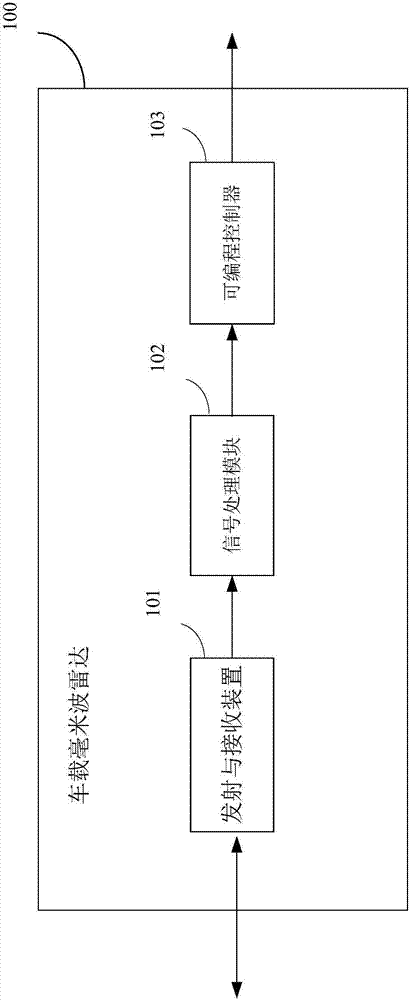
[0021] The invention adopts the vehicle-mounted millimeter wave radar to realize the vehicle door opening alarm. Millimeter wave radar refers to the radar that works in the millimeter wave band. It emits electromagnetic waves with a wavelength of about 1-10mm and a frequency of about 30G-300GHz (Gigahertz), with specific waveforms and modulation methods, and receives and analyzes the surroundings. The electromagnetic wave signal reflected by the object is used to calculate the distance, direction, speed and size of the surrounding objects. According to the waveform and modulation method of the electromagnetic wave sent by the millimeter wave radar and the processing method of the reflected signal, the millimeter wave radar can include millimeter wave pulse radar, frequency modulated continuous wave radar, and spread spectrum radar.
[0022] figure 1 A schematic structural diagram of an exemplary vehicle-mounted millimeter wave radar that can be used in the present invention is shown. The vehicle-mounted millimeter wave radar 100 may be any type of millimeter wave radar. Such as figure 1 As shown in the figure, the vehicle-mounted millimeter wave radar 100 may generally include a transmitting and receiving device 101, a radar signal processing module 102, and a programmable controller 103.
[0023] The transmitting and receiving device 101 may generally include components or circuits such as a voltage controlled oscillator (VCO), a transmitting antenna and a receiving antenna, an amplifier, a power divider, a mixer, etc., which are used to generate and transmit millimeter wave signals, and receive The return signal reflected by the target object is provided to the radar signal processing module 102 for processing.
[0024] The signal processing module 102 can usually be implemented as a digital signal processor (DSP), and can include other components or circuits, which are used to process the return signal from the transmitting and receiving device 101, mainly to reduce various interferences, including Noise, clutter, object movement compensation, etc. In addition, the signal processing module 102 can also be used to calculate the distance and moving speed of the target object according to the returned signal.
[0025] Specifically, the distance between the target object and the radar can be calculated according to the following formula:
[0026] R=C*T r /2,
[0027] Among them, R represents the distance between the target object and the radar, C represents the speed of light, and T r Indicates the time delay of the return signal relative to the transmitted signal.
[0028] According to the Doppler effect of electromagnetic waves, when the radar signal encounters a moving target object, the frequency of the return signal will change accordingly according to the moving speed of the target object. For the target object moving toward the radar, the frequency of the return signal will increase accordingly; for the target object moving away from the radar, the frequency of the return signal will decrease accordingly. Therefore, the moving speed of the target object relative to the radar can be calculated according to the frequency change of the returned signal relative to the transmitted signal. The formula is:
[0029] V r =C*f d /2*f 0 ,
[0030] Where V r Is the moving speed of the target object, C is the speed of light, f d Is the frequency difference between the return signal and the transmitted signal, f 0 Is the frequency of the transmitted signal.
[0031] The programmable controller 103 can be implemented by a microcontroller (MCU), a field programmable gate array (FPGA) or any other programmable processing device, which can be used to obtain the target and its target from the return signal by analyzing the characteristics of the return signal. Part of the effective scattering area (RCS) and other parameters, according to the effective scattering area and other parameters to identify the target object. As those skilled in the art know, RCS is related to the size, structure, material, and radar wavelength of the target object. The target object can usually be regarded as a combination of multiple basic geometric shapes. Different target objects have different RCS values. combination. Therefore, by processing the return signal to obtain a combination of the RCS values of the target object, the target object can be identified. Specifically, the formula for calculating the RCS of the target object or part of it is:
[0032]
[0033] Where P r Is the power of the return signal, P t Is the power of the transmitted signal, R is the distance between the target object and the radar, λ is the signal wavelength, G is the radar gain, L r Is the loss factor and σ is the RCS of the target object.
[0034] By calculating the RCS and other parameters of the target object and its part, and comparing it with the RCS and other parameters of the various objects and parts stored in the database, the target object can be identified. The parameters such as RCS of various objects and parts of them stored in the database may be obtained by detecting various objects using the vehicle-mounted millimeter wave radar in advance.
[0035] The advantages of vehicle-mounted millimeter-wave radar include: it is not affected by weather conditions and nighttime, and can detect objects at a longer distance (for example, more than 100 meters); the scattering angle is small, so it can detect the direction of the object relative to the vehicle; Determine the nature of the object to identify the object.
[0036] It should be noted that the above description and illustration are only examples of the structure of the vehicle-mounted millimeter-wave radar that can be used in the embodiments of the present invention, and do not limit the vehicle-mounted millimeter-wave radar that can be used in the present invention. The vehicle-mounted millimeter wave radar that can be used in the embodiments of the present invention may have other structures or features, for example, include more, fewer or different components or circuits, have different working mechanisms, and so on.
[0037] Refer now figure 2 , Which shows a vehicle door opening alarm system 200 according to an embodiment of the present invention. Such as figure 1 As shown in the figure, the vehicle door opening warning system 200 includes: an on-board millimeter wave radar 100, which is configured to detect the surrounding area of the vehicle by transmitting millimeter wave signals around the vehicle and receiving and processing the millimeter wave signals reflected by objects around the vehicle The distance of the moving object from the vehicle and the speed of the approaching vehicle; the control module 201 is configured to: in response to detecting that the door is about to open, determine whether the moving object is based on the distance of the moving object from the vehicle and the speed of the approaching vehicle The door is about to be reached; and in response to determining that the moving object is about to reach the door, an alarm message is output.
[0038] The embodiment of the present invention adopts millimeter wave radar to detect moving objects around the vehicle, so it has long detection distance, high detection accuracy and accuracy, fast response speed, not affected by weather and night, and can identify moving objects Etc.
[0039] The vehicle-mounted millimeter wave radar 100 may be as figure 1 The vehicle-mounted millimeter-wave radar shown in and described above may also be vehicle-mounted millimeter-wave radars of other structures or types. There may be one or more vehicle-mounted millimeter-wave radars 100, and they may be installed at appropriate positions on the top, rear, and sides of the vehicle. The vehicle-mounted millimeter-wave radar 100 may be an existing vehicle-mounted millimeter-wave radar, or may be an improved vehicle-mounted millimeter-wave radar based on the existing vehicle-mounted millimeter-wave radar, or may be a redesigned and manufactured vehicle-mounted millimeter-wave radar. Wave radar.
[0040] In some embodiments, the vehicle-mounted millimeter-wave radar 100 is connected to the control module 201 through a vehicle bus, a dedicated line, etc., so as to receive instructions from the control module 201, such as a start instruction, and send it to the control module 201. Send information about the detected location, direction, and speed of moving objects.
[0041] In some embodiments, the vehicle-mounted millimeter-wave radar 100 may be activated after receiving a start instruction from the control module 201 and detect objects around the vehicle. The control module 201 may send the start instruction to the vehicle-mounted millimeter-wave radar 100 when it is detected (for example, through the following body control unit) that the vehicle door is about to open. In other embodiments, the vehicle-mounted millimeter-wave radar 100 may be activated after the vehicle is started, so as to continuously detect objects around the vehicle.
[0042] In some embodiments, the vehicle-mounted millimeter-wave radar 100 may further identify moving objects by processing millimeter-wave signals reflected by objects around the vehicle; accordingly, the control module 201 may further output the information of the identified moving objects. information.
[0043] Specifically, for example, the vehicle-mounted millimeter-wave radar 100 can identify moving objects by comparing radar detection data for moving objects with radar detection data of different types of objects stored in a database.
[0044] The database may be stored in a memory connected to the vehicle-mounted millimeter wave radar 100 or the control module 201, for example. For example, the vehicle-mounted millimeter-wave radar 100 may be used in advance to test various moving and stationary objects such as motorcycles, battery cars, bicycles, cars, pedestrians, walls, pillars, etc., to obtain corresponding radar detection data, that is, by checking the The millimeter wave signal returned by the object is analyzed and processed accordingly, and parameters such as RCS of the returned signal reflecting the nature and characteristics of the object are obtained, thereby forming a database of radar detection data of the different types of objects.
[0045] In this way, it is possible to identify the currently detected radar detection data (for example, the RCS of the current return signal) and the radar detection data (the RCS of the return signal of different types of objects) stored in the database. What kind of object is the moving object.
[0046] The control module 201 can be implemented by any processing unit with appropriate information processing capabilities, such as a microprocessor or a microcontroller. The processing unit may generally include a memory or be connected to a memory. The memory stores software programs and data for configuring the processing unit to perform corresponding operations. The processing unit may load the program and data stored in the memory. The data performs its operations. In other embodiments, the control module 201 may be integrated with the vehicle-mounted millimeter-wave radar 100, for example, integrated in the programmable controller of the vehicle-mounted millimeter-wave radar 100 itself. In still other embodiments, the control module 201 may be implemented as a vehicle-mounted electronic control unit (ECU), which may communicate with the vehicle-mounted millimeter wave radar 100 via a vehicle bus.
[0047] In some embodiments, the control module 201 may be connected to a vehicle bus (for example, a CAN bus), so as to communicate with other vehicle-mounted systems. For example, the control module 201 may receive a signal that the door of the vehicle body control unit is about to open through the vehicle bus. The body control unit may, for example, include a contact sensor installed at the door handle, so that when a person in the car turns the door handle to open the door, the contact sensor generates a corresponding sensing signal, so that the body control unit can generate a corresponding door handle. The open signal is sent to the vehicle bus so as to be received by the control module 201.
[0048] In some embodiments, the control module 201 may calculate the expected arrival time of the moving object to the vehicle based on the distance of the moving object from the vehicle-mounted millimeter wave radar 100 and the speed of the approaching vehicle, and may combine it with The moving direction of the moving object from the vehicle-mounted millimeter wave radar 100 is used to determine whether the moving object is about to reach the door. For example, if the calculated expected time for the moving object to arrive at the vehicle is less than a predetermined threshold (for example, 5 seconds), and the vehicle is located on the extension line of the moving direction of the moving object when the vehicle is opened, then the movement can be determined The object is about to reach the door, that is, the moving object is about to collide with the door. At this time, the control module 201 may output alarm information to remind the personnel in the vehicle.
[0049] In some embodiments, the control module 201 may output the generated alarm information to any one or more of the middle display, middle rearview mirror, head-up display system, instrument panel, and speaker of the vehicle through the vehicle bus. .
[0050] In some embodiments, the control module 201 configured to output alarm information is further configured to: generate a virtual object based on the distance of the detected moving object from the vehicle and the speed of the approaching vehicle, and the nature of the identified moving object. A scene video, wherein the virtual scene video reproduces a virtual scene in which the moving object approaches the vehicle; and the virtual scene video is output to the middle display or middle rearview mirror of the vehicle through a vehicle bus for display.
[0051] For example, in the memory connected to the control module 201, images and video elements of various moving and stationary objects, the vehicles, roads, buildings and other environmental elements required to construct the virtual scene video may be stored in advance. . After the control module 201 receives information about the distance of the moving object from the vehicle and the speed of the approaching vehicle from the millimeter wave radar 100 and the nature of the identified moving object, it can obtain information about the identified moving object from the memory. The image and video elements of the type of the moving object and its environmental elements are used to generate a virtual scene video according to the distance of the moving object from the vehicle and the speed of the approaching vehicle using the image and video elements. The virtual scene video may be similar to a scene in which a moving object approaches a vehicle in reality. For example, it may include the moving object having the distance and moving at the moving speed, the vehicle, and the surrounding environment (such as roads, buildings, etc.). Objects, etc.) images and videos.
[0052] By outputting the virtual scene video to a middle display or a middle rearview mirror (smart rearview mirror) for display, it is possible to more intuitively remind people in the vehicle of moving objects around the vehicle, thereby effectively avoiding the risk of collision. image 3 The virtual scene video displayed at the middle display of the vehicle is schematically shown, in which a scene in which a motorcycle behind the vehicle is continuously approaching the vehicle at a certain speed on the road is reproduced.
[0053] In some other embodiments, the control module 201 configured to output alarm information is further configured to: pass information about the distance of the detected moving object from the vehicle and the speed information of the approaching vehicle as well as the property information of the identified moving object. The vehicle bus is output to the on-board head-up display system, so that the on-board head-up display system displays the pattern of the moving object approaching the vehicle on the front windshield or door glass of the vehicle, as well as the distance and speed information of the moving object.
[0054] As known by those skilled in the art, a vehicle heads-up display system usually includes an image generation unit and a projection unit, and uses the front windshield or door glass of the vehicle as a transparent projection display screen. The image generated by the image generation unit is projected on the front windshield or door glass through the projection unit for display, so that the occupants in the car can see the displayed image and the actual scene in front or side of the car at the same time without lowering their heads.
[0055] The embodiment of the present invention uses the on-board head-up display system to display the pattern of the moving object approaching the vehicle and the distance and speed information of the moving object on the front glass or door glass. The pattern of the moving object approaching the vehicle may be displayed in the form of animation, for example. The pattern of moving objects constantly approaching the vehicle, which can remind the people in the vehicle more conspicuously, thereby effectively avoiding the risk of collision. Figure 4A Schematically shows the pattern of the moving object approaching the vehicle displayed on the front windshield of the vehicle and the distance and speed information of the moving object; Figure 4B It schematically shows the pattern of the moving object approaching the vehicle and the distance and speed information of the moving object displayed on the door glass of the vehicle.
[0056] In a further embodiment, the control module 201 configured to output alarm information is further configured to pass information about the distance of the detected moving object from the vehicle, the speed information of the approaching vehicle, and the identity information of the door to be opened. The vehicle bus is output to the on-board head-up display system, so that the on-board head-up display system displays the pattern of the moving object approaching the vehicle on the door glass of the door to be opened, and the distance and speed information of the moving object. For example, if the control module 201 learns that the left front door of the vehicle is about to open through the vehicle bus and the body control unit, the on-board head-up display system will display the pattern of the moving object approaching the vehicle and the distance of the moving object on the door glass of the left front door. And speed information; if the control module 201 knows that the right rear door of the vehicle is about to open through the vehicle bus and the body control unit, the on-board head-up display system will display the pattern of the moving object approaching the vehicle and the moving object on the door glass of the right rear door Distance and speed information, etc. In this way, when a person in the vehicle wants to open a certain door and get out of the vehicle, they can more easily see the information displayed on the window glass of the door, thereby effectively avoiding the risk of collision.
[0057] In some embodiments, the control module 201 configured to output alarm information is further configured to: output the detected distance of the moving object from the vehicle and the speed information of the approaching vehicle to the vehicle dashboard through the vehicle bus, so that all The vehicle dashboard displays a warning icon indicating that the moving object is approaching the vehicle, as well as distance and speed information of the moving object. By displaying simple information such as the warning icon of the moving object approaching the vehicle and the distance and speed information of the moving object on the vehicle dashboard, the dashboard equipped in most vehicles can be used, which can realize low-cost information to the people in the car. Warning.
[0058] In some embodiments, the control module 201 configured to output alarm information is further configured to: calculate the time when the moving object arrives at the door according to the distance of the moving object from the vehicle and the speed of the approaching vehicle; and in response to the calculation When the time is less than or equal to the threshold, the vehicle horn outputs a start signal through the vehicle bus, so that the vehicle horn emits a warning sound.
[0059] The threshold may be preset by the system or the user. For example, the threshold can be set to 3 seconds. In this way, if the control module 201 calculates that the time for the moving object to reach the car door is less than 3 seconds, it can output a start signal to the vehicle horn, so that the vehicle horn can sound an alarm, thereby to the vehicle occupants A stronger alarm is issued to more effectively avoid the risk of collision.
[0060] The technical features in the above-mentioned embodiments of the present invention can be combined arbitrarily in an appropriate manner. For example, the technical features of displaying the warning information in the middle display or the middle rearview mirror of the vehicle, the technical features of displaying the warning information in the on-board head-up display system, and/or the displaying in the dashboard The technical feature of the warning information can be combined with the technical feature of emitting a warning sound through a vehicle horn. For example, when the expected time for the moving object to arrive at the vehicle calculated by the control module 201 is less than a larger first threshold (for example, 5 seconds), it can be displayed on the middle display, middle rearview mirror, head-up display system or dashboard first. Warning information; and when the expected time for the moving object to arrive at the vehicle calculated by the control module 201 is less than the second smaller threshold (for example, 3 seconds), an alarm can be sounded through the vehicle horn to remind the people in the vehicle of greater relatives Risk of collision.
[0061] In addition, in some embodiments of the present invention, when the control module 201 determines that the object is about to reach the door, it may further issue an instruction to lock the door to the body control unit to more effectively avoid the risk of collision. The vehicle body control unit may unlock the vehicle door after a predetermined time or after receiving an unlocking instruction issued by a person in the vehicle (for example, a release instruction issued through a specific button on a vehicle center console or the like).
[0062] The vehicle door opening alarm system according to the embodiment of the present invention is described above with reference to the accompanying drawings. It should be pointed out that the above description is only an example, not a limitation of the present invention. In other embodiments of the present invention, the system may have more, fewer, or different modules, and the connections, inclusions, and functions among the modules may be different from those described and illustrated. For example, in some embodiments, the vehicle-mounted millimeter wave radar 100 and the control module 201 may be integrated into a single module. For another example, in some embodiments, part of the functions in the control module 201 may be completed by separate components, for example, the function of generating and displaying virtual scene videos may be completed by a separate virtual reality module. For another example, in some embodiments, the vehicle door opening alarm system 200 may further include any one or more of the body control unit, middle display, middle rearview mirror, head-up display system, instrument panel, and vehicle horn, Or it may also include a dedicated display or speaker for the system, etc. All these changes are within the scope of the present invention.
[0063] Although the embodiments of the present invention have been described above with reference to the accompanying drawings, those skilled in the art can understand that the above description is only an example, not a limitation of the present invention. Various modifications and variations can be made to the embodiments of the present invention while still falling within the spirit and scope of the present invention, which is only determined by the appended claims.
PUM


Description & Claims & Application Information
We can also present the details of the Description, Claims and Application information to help users get a comprehensive understanding of the technical details of the patent, such as background art, summary of invention, brief description of drawings, description of embodiments, and other original content. On the other hand, users can also determine the specific scope of protection of the technology through the list of claims; as well as understand the changes in the life cycle of the technology with the presentation of the patent timeline. Login to view more.
Similar technology patents
Semiconductor-laser narrow pulse driving circuit and working method thereof
Owner:SHANDONG UNIV
Method for preparing organic field effect transistor dielectric layer by using plasma crosslinking technology
Owner:FUDAN UNIV
Prepn process of cyclic phosphonate compound
Owner:SHENYANG RES INST OF CHEM IND
Method and device for calling local interface of virtual machine
Owner:SHENZHEN NETCOM ELECTRONICS CO LTD
Convenient-to-clean anti-noise high-stirring-force chemical reaction tank
Owner:ZHENGZHOU SOUQU INFORMATION TECH CO LTD