
Scattering device and manufacturing method thereof, luminescence device, projection system and illumination system

A light-emitting device and manufacturing method technology, applied in projection devices, optics, optical components, etc., can solve the problem of very high control requirements for the surface morphology of the scattering sheet, and achieve the effect of a small scattering angle

Active Publication Date: 2017-12-05
SHANGHAI BLUE LAKE LIGHTING TECH CO LTD
View PDF2 Cites 0 Cited by
  • Summary
  • Abstract
  • Description
  • Claims
  • Application Information

AI Technical Summary

Problems solved by technology

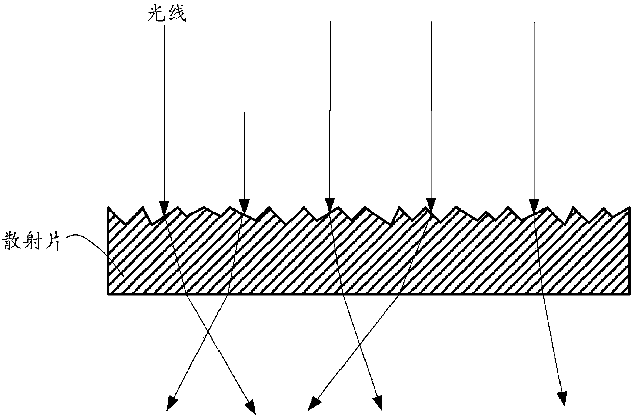
However, for lighting applications, it is often required that the spot must be less than 1mm, or even less than 0.5mm. At this time, the half-angle of scattering needs to be less than 3 degrees, or even less than 1.5 degrees, that is, the diffuser should diffuse the parallel laser light to a small light cone of 1.5 degrees. , which requires very high control of the surface morphology of the scattering sheet, which is difficult to achieve with the current technology

Method used


Image

  • Scattering device and manufacturing method thereof, luminescence device, projection system and illumination system
  • Scattering device and manufacturing method thereof, luminescence device, projection system and illumination system
  • Scattering device and manufacturing method thereof, luminescence device, projection system and illumination system

Examples


Embodiment 1

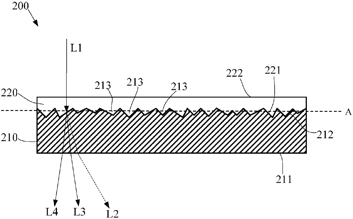
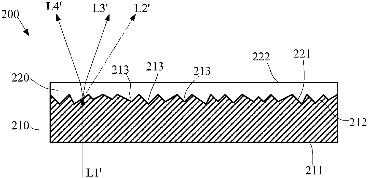
[0032] see Figure 2a and Figure 2b , Figure 2a and 2b is a schematic structural diagram of an embodiment of the scattering device in the embodiment of the present invention. Such as Figure 2a and 2b As shown, the scattering device 200 includes a transparent inorganic substrate 210 (shaded area) and a transition medium 220 (unshaded area).

[0033] The transparent inorganic substrate 210 includes a first surface 211 and a second surface 212 opposite to each other. Transparency in transparent inorganic substrates means that the substrate material is transparent and low-absorbing to the light to be scattered; there are many options for inorganic substances, such as silicon oxide (quartz), aluminum oxide, titanium oxide, etc., and may also be A mixture of various inorganic components, such as glass. The first surface is a plane, and the second surface 212 is a rough surface, and the rough surface has a plurality of micro depressions 213 . Generally speaking, whether ch...

Embodiment 2

[0061] see image 3 , image 3 is a schematic structural diagram of another embodiment of the scattering device in the embodiment of the present invention. Such as image 3 As shown, the scattering device 300 includes a transparent inorganic substrate 310 (shaded area) and a transition medium 320 (unshaded area). The base 310 includes a first surface 311 and a second surface 312 opposite to each other, and the second surface 312 is a rough surface. The transition medium 320 covers the rough surface of the substrate 310 , and the transition medium 320 includes a third surface 321 and a fourth surface 322 opposite to each other.

[0062] The differences between this embodiment and the embodiment shown in Figure 2 include:

[0063] The fourth surface 322 of the transition medium is an arc surface, specifically a convex surface, and the convex surface is equivalent to a lens. The scattering device 300 can be regarded as two optical elements divided by the surface B, the upper...

Embodiment 3

[0067] From the analysis in Embodiment 1, it can be seen that the transition medium does not necessarily have to fill the micro-depressions, but as long as there are micro-depressions filled, and the upper surface of the transition medium filled with micro-depressions is partially flat, the light L1 incident on this plane is The scattering angle can be reduced by the scattering device. Therefore, the present invention also provides another embodiment. see Figure 4a , Figure 4a is a schematic structural diagram of another embodiment of the scattering device in the embodiment of the present invention. Such as Figure 4a As shown, the scattering device 400 includes a transparent inorganic substrate 410 (shaded area) and a transition medium 420 (unshaded area).

[0068] The transparent inorganic substrate 410 includes a first surface 411 and a second surface 412 opposite to each other. The second surface 412 is a rough surface, and the rough surface has a plurality of micro ...


PUM


Abstract

The embodiment of the invention discloses a scattering device and a manufacturing method thereof, a luminescence device, s projection system and an illumination system. The scattering device comprises: a transparent inorganic substance substrate comprising a first surface and a second surface which are oppositely arranged, wherein the at least part of the second surface is a rough surface which have a plurality of miniature recesses; transition medium which is located in the miniature recesses of the rough surface and does not exceed the located miniature recesses, wherein the transition medium is tightly contacted with the inner walls of the miniature recesses to form a transition medium-substrate interface, and at least part of the upper surface of the transition medium is a plane, the refractive index of the transition medium satisfies: (img file='dest_path_image002. TIF' wi='297' he='27' / ), or (img file='dest_path_image004. TIF' wi='394' he='27' / ), the angle of inclination of the miniature recesses of the substrate is (img file='dest_path_image006. TIF' wi='14' he='18' / ), the refractive index of the substrate is (img file='dest_path_image008. TIF' wi='17' he='18' / ), and the refractive index of the transition medium is (img file='dest_path_image010. TIF' wi='18' he='19' / ). According to the embodiment of the invention, the scattering angle is small.

Description

technical field [0001] The invention relates to the technical field of illumination and display, in particular to a scattering device, a manufacturing method thereof, a light emitting device, a projection system and an illumination system. Background technique [0002] In the prior art, using laser to excite fluorescent powder to generate received light is a common means to realize light source. In order to increase the brightness (energy density), the laser light is focused on the phosphor through a lens. However, due to the high collimation of the laser beam, a very small light spot can be formed after focusing, and the energy density on this light spot is very high, which often exceeds the tolerance range of the phosphor, resulting in thermal quenching. In order to solve this problem, in the prior art, a scattering sheet is placed on the optical path of the laser to reduce its collimation, thereby enlarging the spot focused on the phosphor. [0003] Diffusers commonly...

Claims


Application Information

Patent Timeline
Patent Type & Authority Applications(China)
IPC IPC(8): G02B5/02G03B21/20
CPCG02B5/0221G02B5/0278G03B21/2053
Inventor 不公告发明人
Owner SHANGHAI BLUE LAKE LIGHTING TECH CO LTD
Learn More