
An infrared laser beam detector

An infrared laser and detector technology, applied in instruments, alarms, anti-theft alarms, etc., can solve the problems of reduced debugging work efficiency, weak penetration ability, adjustment of up and down direction and adjustment of left and right direction interference, etc., to achieve debugging work efficiency Elevation, light path control is easy to control, and the effect of improving the shooting distance

Active Publication Date: 2017-03-22
BEIJING HONGDA JINGDIAN ELECTRONICS TECH
View PDF5 Cites 0 Cited by
  • Summary
  • Abstract
  • Description
  • Claims
  • Application Information

AI Technical Summary

Problems solved by technology

However, infrared radiation detectors using ordinary light sources have defects such as non-concentrated infrared light energy, large divergence angle, weak penetration ability, and high emission power consumption. Disadvantages such as high false alarm rate, large crosstalk, and high infrared power in the case of long-distance shooting
The following technical problems exist in the infrared through-beam detectors using ordinary infrared light sources: (1) There is crosstalk between adjacent infrared through-beam detectors; The weather; (3) The shooting distance is short, and it cannot adapt to the long-distance shooting; (4) The transmission power is large and the energy consumption is high, which is not conducive to energy saving;
[0003] In addition, the control of the laser beam direction of some existing infrared laser beam detectors is complex, and the beam emission direction is realized by multi-point adjustment, and the adjustment of the vertical direction and the adjustment of the left and right directions interfere with each other
In the debugging process, there are disadvantages such as difficult control of the optical path, complicated debugging, and poor controllability, which reduce the efficiency of debugging

Method used


Image

  • An infrared laser beam detector
  • An infrared laser beam detector
  • An infrared laser beam detector

Examples


Embodiment Construction

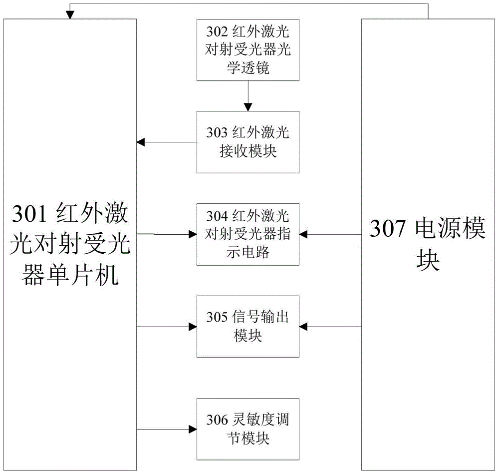
[0032] Such as figure 1 As shown, the infrared laser on-shooting detector of the present invention includes an infrared laser on-shooting light projector 101 and an infrared laser on-shooting light receiver 102; Laser beam with adjustable beam direction. The infrared laser beam receiving device 102 receives the laser beam emitted by the infrared laser beam projector 101, and the infrared laser beam receiver microcontroller counts the lost laser beam pulses.

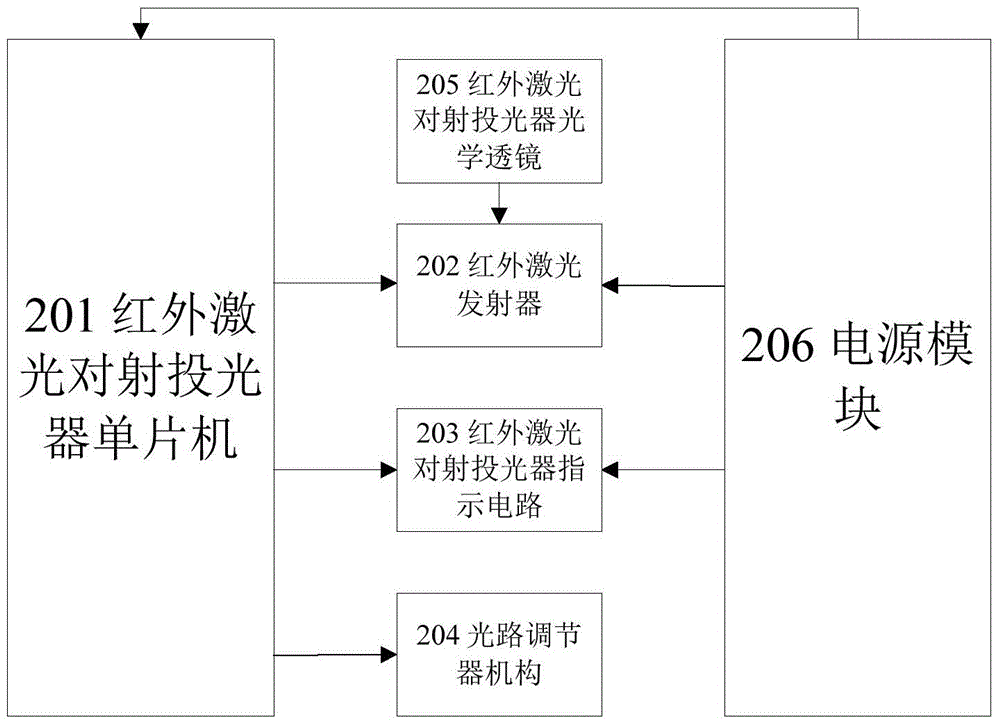
[0033] Such as figure 2 As shown, the infrared laser projector 101 is composed of an infrared laser projector microcontroller 201, an infrared laser transmitter 202, an infrared laser projector indicating circuit 203, an optical path adjustment mechanism 204, an infrared laser projector optical lens 205, and a power supply module 206. composition;

[0034] Static connection: the single-chip microcomputer 201 of the infrared laser projector, the indication circuit 203 of the infrared laser projector, and the power supp...


PUM


Abstract

The invention provides an infrared laser opposite emission detector. The infrared laser opposite emission detector detects whether a pulse laser beam affecting emission of an infrared laser opposite emission projector is normally emitted towards an infrared laser opposite emission receiver in a wide climatic environment, and output signals are potential-free contacts. The infrared laser opposite emission detector is composed of the infrared laser opposite emission projector and the infrared laser opposite emission receiver. According to the infrared laser opposite emission projector, an infrared laser emitter is controlled by an infrared laser opposite emission projector single-chip microcomputer to emit the pulse laser beam. According to the infrared laser opposite emission receiver, a single-chip microcomputer processes the pulse laser beam and outputs potential-free contact normally open / closed signals.

Description

technical field [0001] The invention relates to an infrared laser beam-to-beam detector in the field of security technology prevention, which is applied to surrounding alarms. Background technique [0002] In the field of security technology prevention, the common infrared radiation method has been widely used. However, infrared radiation detectors using ordinary light sources have defects such as non-concentrated infrared light energy, large divergence angle, weak penetration ability, and high emission power consumption. Disadvantages such as high false alarm rate, large crosstalk, and high infrared power in the case of long-distance shooting. The following technical problems exist in the infrared through-beam detectors using ordinary infrared light sources: (1) There is crosstalk between adjacent infrared through-beam detectors; The weather; (3) The shooting distance is short, and it cannot adapt to the long-distance shooting; (4) The transmission power is large and the ...

Claims


Application Information

Patent Timeline
Patent Type & Authority Patents(China)
IPC IPC(8): G08B13/183
CPCG08B13/183
Inventor 叶慧秀江永年张腾
Owner BEIJING HONGDA JINGDIAN ELECTRONICS TECH
Learn More