
Method of Constructing Steel-concrete Composite Beams Using Cross Cables

A steel-concrete composite beam, cross-type technology, applied in bridges, bridge construction, erection/assembly of bridges, etc., can solve problems such as material waste, achieve broad application prospects, uniform force, and reduce engineering costs.

Active Publication Date: 2019-08-06
HENAN PROVINCIAL COMM PLANNING & DESIGN INST CO LTD +2
View PDF5 Cites 0 Cited by
  • Summary
  • Abstract
  • Description
  • Claims
  • Application Information

AI Technical Summary

Problems solved by technology

However, if limited by construction conditions, when it is impossible or unsuitable to erect supports at the bridge site, construction methods without supports are often used for construction. During the construction of traditional steel-concrete composite beams without supports, the steel beams need to bear their own weight and construction loads. and concrete self-weight, etc., in order to meet the construction requirements, the rigidity of the steel beam is required to be greater than that of the dead-load composite beam, which causes a waste of materials to a certain extent for the steel-concrete composite beam that bears the same load after the bridge is completed

Method used


Image

  • Method of Constructing Steel-concrete Composite Beams Using Cross Cables
  • Method of Constructing Steel-concrete Composite Beams Using Cross Cables
  • Method of Constructing Steel-concrete Composite Beams Using Cross Cables

Examples


Embodiment Construction

[0034] The construction method of the present invention will be described in more detail below by taking the steel-concrete continuous composite beam with seven holes and one connection as an example, wherein the span range of each steel beam unit is 30-120m, which is more suitable:

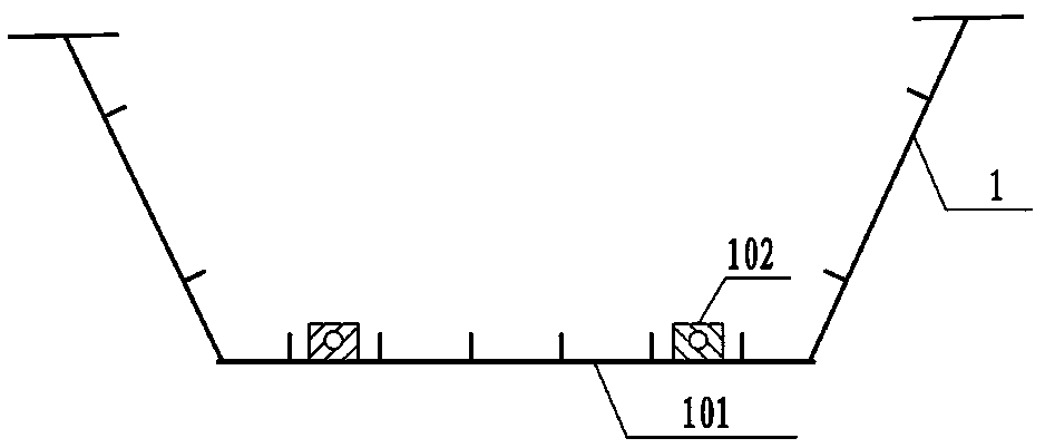
[0035] In the first step, according to the design requirements, the steel beam unit 1 for each hole is prefabricated, and six temporary hanging pieces 102 are arranged at intervals on the bottom plate 101 of the steel beam unit, such as figure 1 shown; if the span is large, the number of temporary hanging pieces can be increased;

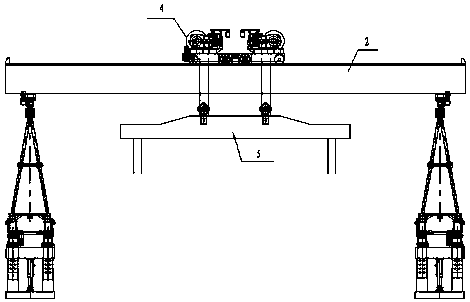
[0036] In the second step, according to the span of the steel beam unit in each hole, six groups of cable devices 3 are designed at intervals on the crossbeam of the bridge erecting machine 2, and the bottom of the cable 301 of each cable device 3 is provided with a corresponding temporary hanging piece 102. Hanging buckle 302, wherein the number of cable devices 3 is ...


PUM


Abstract

The invention discloses a method of constructing a steel-concrete composite steel beam adopting a crossing type inhaul cable. The method includes the steps that firstly steel beam units are prefabricated, a plurality of temporary suspension pieces are arranged at the steel beam bottom plates, inhaul cable devices are correspondingly arranged at bridge steel beam erection machines simultaneously, after a first steel beam crossing the bridge opening is erected to be on position, suspension clasps at the bottom portions of the inhaul cables of the bridge steel beam erection machines and the suspension pieces of the steel beam bottom plates are mutually connected in a crossing mode to enable the inhaul cables of the midspan area to form a crossing cable-stayed condition; then the inhaul cablestress is stretched to a preset value to be locked; prefabricated concrete bridge deck slabs are installed; bridge deck slab wet joint concrete are poured; when the bridge deck slab wet joint concreteachieves the designed strength, the connection of the inhaul cables and the suspension pieces are relieved; a second steel beam crossing the bridge opening is erected, the construction of steel beamscrossing the two bridge openings is completed; and in turn, the construction of the whole bridge is completed. According to the method of constructing the steel-concrete composite steel beam adoptingthe crossing type inhaul cable, the material using efficiency of traditional non-bracket construction steel-concrete composite steel beam can be improved, the convenient and rapid construction and aseries of advantages are possessed, and wide application prospects in large and middle span composite beam erection are possessed.

Description

technical field [0001] The invention relates to a construction method of a steel-concrete composite beam, in particular to a method for constructing a steel-concrete composite beam by using crossed cables. Background technique [0002] The steel-concrete composite beam has a series of advantages such as light structure, large spanning capacity, and fast construction speed. It can meet the construction requirements of urban viaducts and long bridges across rivers and seas to the greatest extent, and has been more and more widely used in modern bridge structures. [0003] Due to the different construction procedures and construction methods of steel-concrete composite beams, their stress states are also different. According to the stress state of the composite beam construction, it can be divided into two types of structures: 1) Live-loaded composite beams, that is, construction without supports. During the construction process, the steel beams and concrete are all borne by th...

Claims


Application Information

Patent Timeline
Patent Type & Authority Patents(China)
IPC IPC(8): E01D21/00
CPCE01D21/00
Inventor 李斐然李小对王涛谢冬歌袁波张士红李庆贤李尉敏
Owner HENAN PROVINCIAL COMM PLANNING & DESIGN INST CO LTD
Learn More