Construction and installation method of floor drain
An installation method and technology of floor drains, applied to water supply devices, waterway systems, drainage structures, etc., can solve problems such as trouble, slow water leakage, unsanitary, etc., and achieve the effect of accurate location and prevention of blockage
- Summary
- Abstract
- Description
- Claims
- Application Information
AI Technical Summary
Problems solved by technology
Method used
Image

Examples
Embodiment Construction
[0029] The present invention will be described in further detail below by means of specific embodiments:
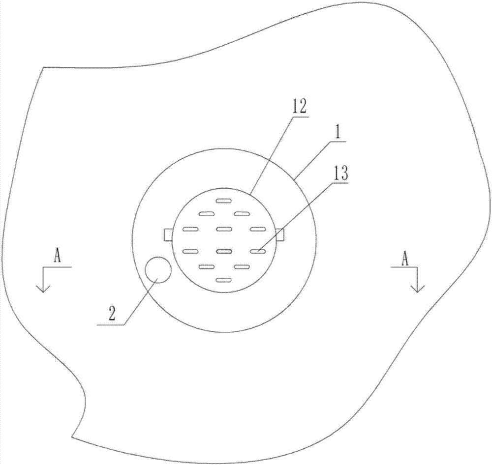
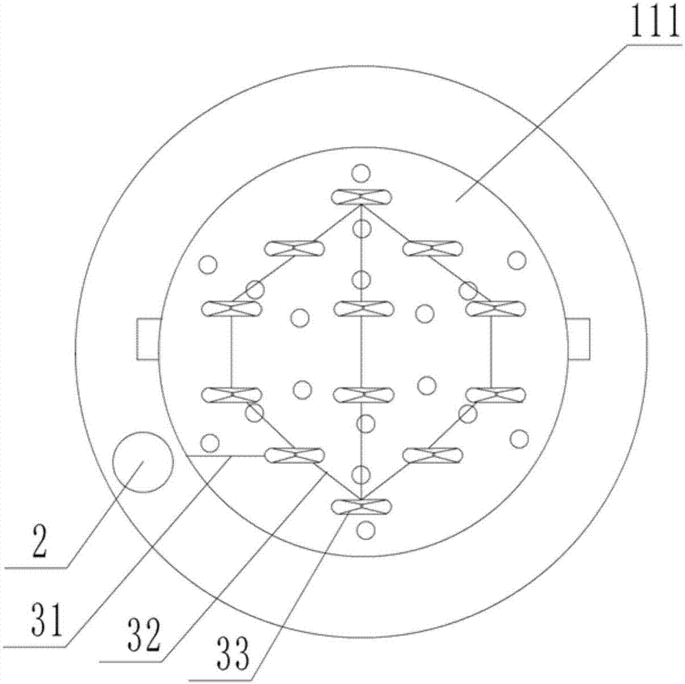
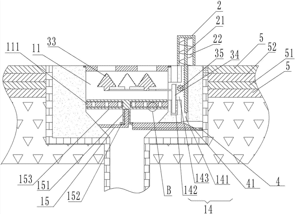
[0030] Instructions attached figure 1 , figure 2 , image 3 and Figure 4 The reference signs in include: floor drain body 1, leakage channel 11, cover plate 12, leakage hole 13, filter plate 111, friction protrusion 1111, rubber protrusion 2, power rod 21, return spring 22, cavity 14, rod Cavity 141, rack cavity 142, gear cavity 143, L-shaped support column 15, rotating column 151, rotating ring gear 152, blade 153, cross bar 31, support frame 32, tapered top 33, ejection rack 34, gear 35, slide spring 4, slide bar 41, leveling layer 5, protective layer 51, waterproof layer 52.
[0031] Such as figure 1 , figure 2 , image 3 and Figure 4 Shown, in order to achieve the above object, basic scheme of the present invention is as follows:
[0032] A method for construction and installation of a floor drain. The floor drain includes a floor drain body 1. A water le...
PUM
 Abstract
Description
Claims
Application Information
 - Generate Ideas
- Intellectual Property
- Life Sciences
- Materials
- Tech Scout
- Unparalleled Data Quality
- Higher Quality Content
- 60% Fewer Hallucinations
Browse by: Latest US Patents, China's latest patents, Technical Efficacy Thesaurus, Application Domain, Technology Topic, Popular Technical Reports.
© 2025 PatSnap. All rights reserved.Legal|Privacy policy|Modern Slavery Act Transparency Statement|Sitemap|About US| Contact US: help@patsnap.com