Novel LED lamp light-guiding structure

A technology of LED lamp and light guide structure, which is applied in the direction of light source, semiconductor device of light-emitting element, lighting device, etc., can solve the problems of affecting the uniformity of light output, complicated manufacturing process, low space utilization rate, etc., and achieves uniform and moderate brightness. The effect of good uniformity and less light loss

Pending Publication Date: 2018-05-01
CHANGZHOU XINGYU AUTOMOTIVE LIGHTING SYST
View PDF0 Cites 3 Cited by
  • Summary
  • Abstract
  • Description
  • Claims
  • Application Information

AI Technical Summary

Problems solved by technology

Nowadays, in many LED lights, there are problems of uneven light guide and large light loss; in addition, the traditional light guide structure adopts a light guide plate structure with light entering from the side and dots on the back, and a diffuser plate and a reflective film must also be installed , with many material configurations, complex manufacturing process, large volume, and low space utilization; in addition, there are some traditional LED lamps where the light emitting surface of the light guide block is a tooth surface with complex shapes, and there are many inferior products in production, mainly Injection defects in appearance, weld lines, flow marks, shrinkage, etc., poor appearance quality, and many internal impurities also affect the uniformity of light output

Method used


Image

  • Novel LED lamp light-guiding structure
  • Novel LED lamp light-guiding structure
  • Novel LED lamp light-guiding structure

Examples


Embodiment Construction

[0026] The present invention is described in further detail now in conjunction with accompanying drawing. These drawings are all simplified schematic diagrams, which only illustrate the basic structure of the present invention in a schematic manner, so they only show the configurations related to the present invention.

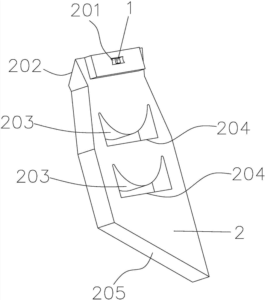
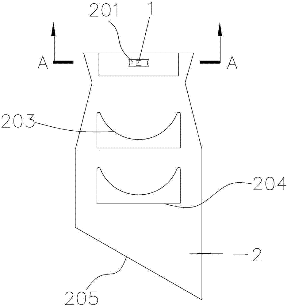
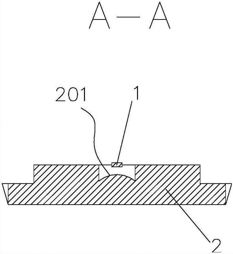
[0027] Such as Figure 1-Figure 4 Shown is a specific embodiment of a novel LED light guide structure of the present invention, which includes an LED light source 1 and a light guide block 2. The light guide block 2 is provided with an inlet convex surface 201 and a total reflection surface 202, and the LED light source 1 faces The inlet convex surface 201 and the total reflection surface 202 are used for total reflection of the refracted light from the inlet convex surface 201; the light guide block 2 is evenly distributed with a number of light-gathering grooves in the reflection direction of the total reflection surface 202, and the light-gathering grooves ...


PUM


Abstract

The invention belongs to the technical field of light guiding of LED lamps, and particularly relates to a novel LED lamp light-guiding structure. The novel LED lamp light-guiding structure comprises an LED light source and a light guiding block, the light guiding block is provided with an inlet convex face and a total reflection face, the LED light source faces the inlet convex face, and the totalreflection face is used for total reflection of refraction light rays of the inlet convex face; a plurality of light condensation grooves are evenly distributed on the light guiding block, each lightcondensation groove comprises a light condensation convex face and a receiving flat face facing the light condensation convex face, and the light condensation convex faces and the receiving flat faces are sequentially arranged in the positive direction of reflection light rays of the total reflection face; and a light-out flat face is arranged at the tail end, in the positive direction of the reflection light rays of the total reflection face, of the light guiding block, and the receiving flat faces and the light-out flat face are oppositely arranged. The novel LED lamp light-guiding structure has the beneficial effects that the effect of the uniform light rays can be achieved, the light ray loss is very small, and the light ray utilization rate is increased; material configuration is less, the structure is simple, the size is small, and the space utilization rate is increased; and a traditional sawtooth-shaped structure is omitted, manufacturing is convenient, the quality after forming is good, the light uniformity is good, and the appearance of the light guiding structure is optimized.

Description

technical field [0001] The invention belongs to the technical field of LED light guides, and in particular relates to a novel LED light guide structure. Background technique [0002] At present, LED light guide technology has been used in various industries, such as in the automotive lighting industry. With the development of the automobile industry, automobiles have become an indispensable means of transportation and transportation for human society, and automobiles and lamps are inseparable. Lamps are responsible for two functions of lighting and indicating signals. It can be said that there are car lights. The diversification of modern automobile shapes makes the user's requirements for the experience of headlights also increase day by day. At present, some high-end models are already equipped with LED lights. LEDs have the advantages of small size, energy saving and environmental protection. Therefore, in the future, LEDs will be an inevitable trend as a light source fo...

Claims


Application Information

Patent Timeline
IPC IPC(8): F21K9/61F21Y115/10
Inventor 李朝晖刘奇伟田佳
Owner CHANGZHOU XINGYU AUTOMOTIVE LIGHTING SYST
Why Eureka
Try Eureka