
Sensor of oil burning pump

A sensor and fuel pump technology, applied in instruments, liquid level indicators, float level indicators, etc., to achieve the effect of solving the need for accurate display of instruments

Inactive Publication Date: 2018-05-01
ANHUI JIANGHUAI AUTOMOBILE GRP CORP LTD
View PDF3 Cites 0 Cited by
  • Summary
  • Abstract
  • Description
  • Claims
  • Application Information

AI Technical Summary

Problems solved by technology

[0003] The purpose of the present invention is to provide a fuel pump sensor to solve the technical problems in the prior art. It can provide more resistance values ​​for the meter, which is very suitable for the design of flat fuel tank sensors, and solves the demand for accurate display of the meter. have great advantages

Method used


Image

  • Sensor of oil burning pump
  • Sensor of oil burning pump
  • Sensor of oil burning pump

Examples


Embodiment Construction

[0021] The embodiments described below by referring to the figures are exemplary only for explaining the present invention and should not be construed as limiting the present invention.

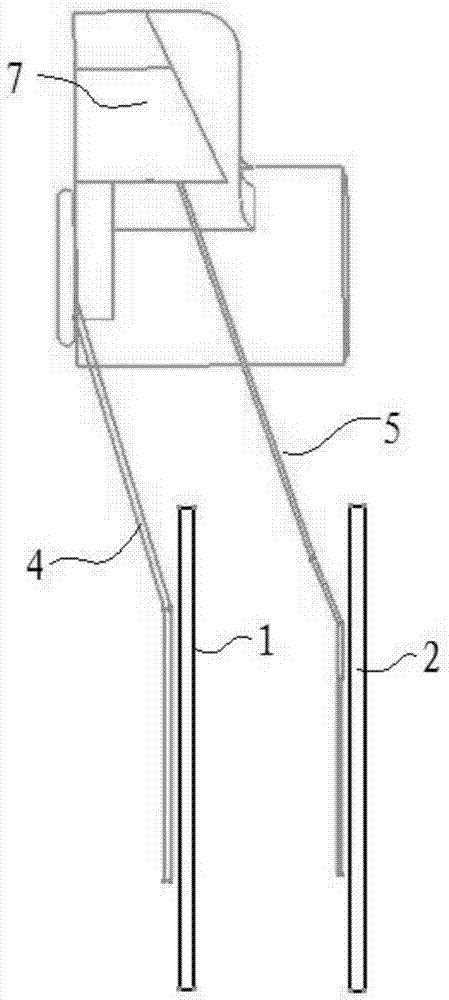
[0022] Such as Figure 3 to Figure 6 As shown, the embodiment of the present invention provides a fuel pump sensor, including a casing and a float rod assembly 7 hinged on the casing, the float rod assembly 7 is rotatably fixed on the casing through a bearing, and the float One end of the rod assembly 7 is connected with a float, and when the oil level changes, the float rod assembly 7 is controlled by the float to rotate, and the housing is provided with a first resistance sheet 1 and a second resistance sheet 2, and the first resistance sheet 1 and the The second resistance piece 2 is electrically connected to the input lead 3 after being connected in parallel, and the electrical connection end of the float rod assembly 7 is equipped with a first reed 4 for contacting with the first resista...


PUM


Abstract

The invention discloses a sensor of an oil burning pump. The sensor comprises a shell and a floater rod component which is hinged to the shell, a first resistance sheet and a second resistance sheet are arranged on the shell, are in parallel connection with each other and then are electrically connected with an input lead, an electric connection end of the floater rod component is provided with afirst reed which is used for being in contact with the first resistance sheet and a second reed which is used for being in contact with the second resistance sheet, and the first reed and the second reed are in parallel connection with each other and then are electrically connected with an output lead. Compared with the prior art, the sensor of the oil burning pump has the advantages that the tworesistance sheets and the two reeds are arranged, under the situation that the height difference of the upper surface and the lower surface of the inner side of an oil tank and the rotation radius ofthe floater rod component are fixed, the number of resistance values which can be provided by the sensor of the oil burning pump is far higher than that of resistance values provided by a sensor of atraditional oil burning pump, and the sensor of the oil burning pump is extremely suitable for design of a flat oil tank sensor and has a great advantage in meeting the demand of a meter for precise display.

Description

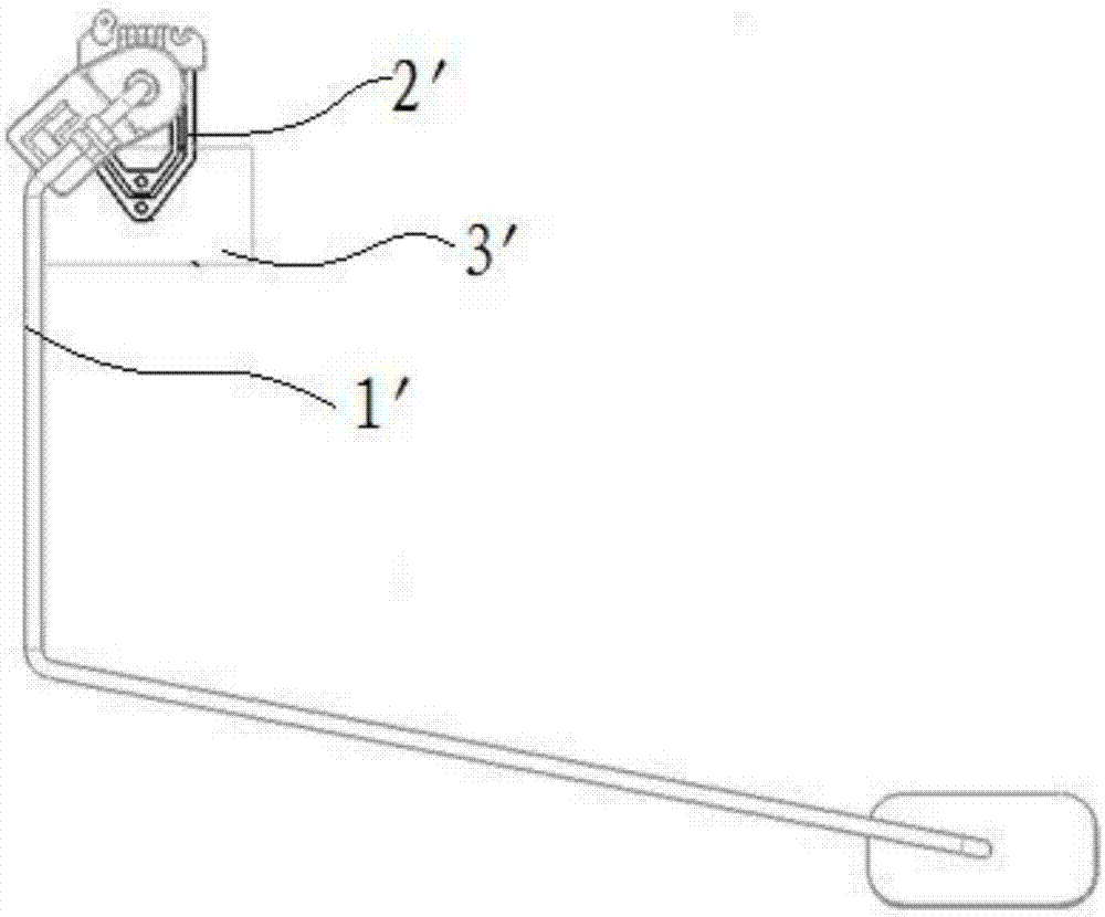
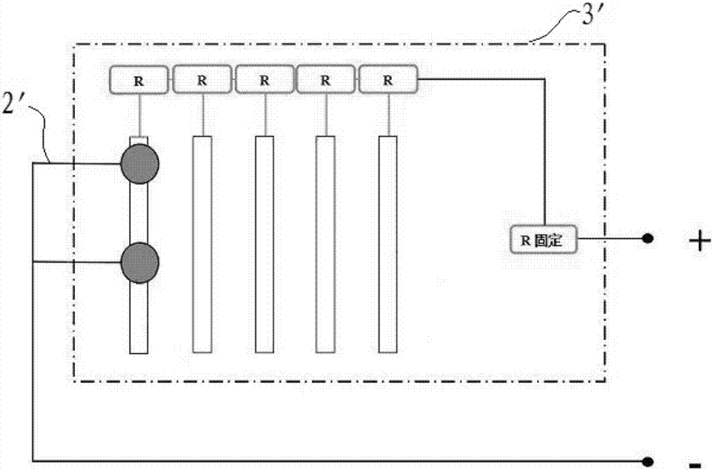
technical field [0001] The invention relates to the technical field of fuel level sensors, in particular to a fuel pump sensor. Background technique [0002] Such as figure 1 A schematic structural diagram of a fuel pump sensor in the prior art is shown, and the fuel pump sensor is mainly composed of a float rod assembly 1 ′, a resistor plate 2 ′ and a reed 3 ′. When the oil level changes, the float rod assembly 1' of the fuel pump sensor will rotate, and this rotation will drive the contact on the reed 3' to slide on the resistance sheet 2', and then produce different resistance values ​​to output to meter. However, with the use of automobiles, consumers have put forward certain requirements for accurate display of oil quantity on instruments. The position displayed by each meter has a unique resistance value corresponding to it in the oil pump sensor. If the display accuracy of the meter is improved (regardless of the influence of the meter itself), more resistance valu...

Claims


Application Information

Patent Timeline
Patent Type & Authority Applications(China)
IPC IPC(8): G01F23/36
CPCG01F23/363
Inventor 马国祥穆海宁陈强范标漆杰童元赵少锋王文
Owner ANHUI JIANGHUAI AUTOMOBILE GRP CORP LTD
Learn More