Thermoreflectance test method and system

A reflection coefficient, photothermal technology, applied in thermometers, measuring devices, measuring heat and other directions, can solve the problem of difficulty in ensuring the measurement effect of different materials, and achieve the goal of being suitable for large-scale promotion and use, improving accuracy and temperature measurement efficiency, The effect of improving accuracy

Active Publication Date: 2018-05-01
THE 13TH RES INST OF CHINA ELECTRONICS TECH GRP CORP
View PDF5 Cites 15 Cited by
  • Summary
  • Abstract
  • Description
  • Claims
  • Application Information

AI Technical Summary

Problems solved by technology

[0008] The purpose of the embodiments of the present invention is to provide a photothermal reflection temperature measurement method, which aims to solve the problem that it is difficult to ensure that different materials have good measurement results when the area to be measured includes a variety of different materials. Simultaneous measurement of many different materials, reducing C TR Loss, improve the temperature measurement accuracy when measuring multiple different materials at the same time by light and heat reflection

Method used


Image

  • Thermoreflectance test method and system
  • Thermoreflectance test method and system
  • Thermoreflectance test method and system

Examples


Embodiment 1

[0039] The photothermal reflection temperature measurement method in this embodiment is described in detail as follows:

[0040] The light and heat reflectance coefficient C of the area to be tested TR calibration;

[0041] Modulate the outgoing light of light sources with different wavelengths, and project the modulated outgoing light to the area to be tested;

[0042] Receive the reflected light of the area to be tested, and demodulate the reflected light to obtain reflected light signals of different wavelengths;

[0043] Calculate the reflected light signals of different wavelengths to obtain temperature test information.

[0044] The photothermal reflection temperature measurement method of this embodiment uses multi-wavelength probe light to simultaneously measure the temperature of the area to be measured including a variety of different materials, and select C according to the characteristics of different materials. TR The largest wavelength is used for temperature ...

Embodiment 2

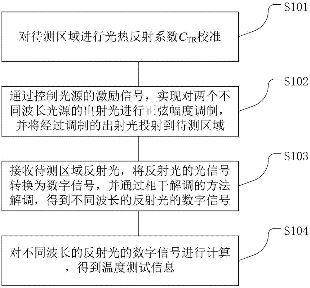
[0059] see figure 1 , the photothermal reflection temperature measurement method in the present embodiment is described in detail as follows:

[0060] S101: Measure the light and heat reflection coefficient C of the area to be measured TR calibration;

[0061] S102: By controlling the excitation signal of the light source, the sinusoidal amplitude modulation of the outgoing light of two light sources with different wavelengths is realized, and the modulated outgoing light is projected to the area to be measured;

[0062] S103: Receive the reflected light of the area to be measured, convert the optical signal of the reflected light into a digital signal, and demodulate it through a coherent demodulation method to obtain digital signals of reflected light of different wavelengths;

[0063] S104: Calculate the digital signals of reflected light with different wavelengths to obtain temperature test information.

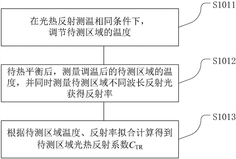
[0064] Preferably, see figure 2 , step S101 includes:

[0065]...

Embodiment 3

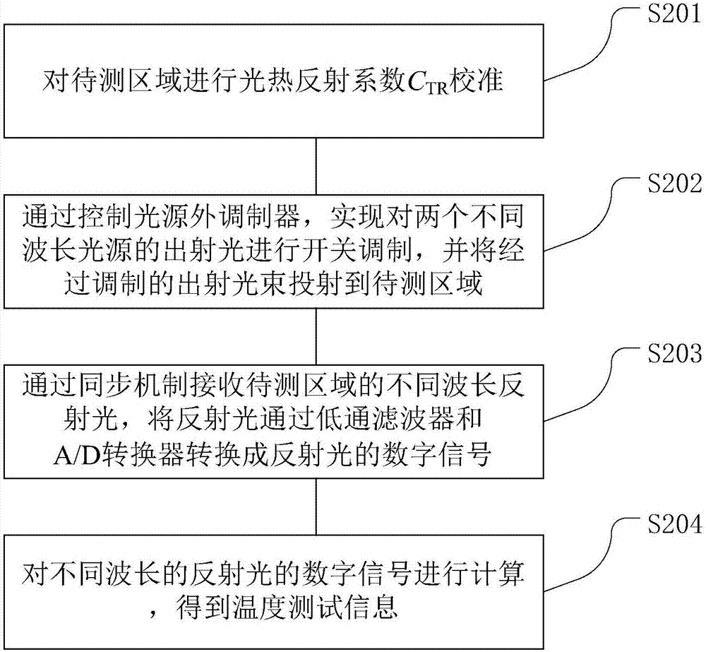
[0073] see image 3 , the photothermal reflection temperature measurement method in the present embodiment is described in detail as follows:

[0074] S201: Measure the light and heat reflection coefficient C of the area to be measured TR calibration;

[0075] S202: By controlling the external modulator of the light source, switching and modulating the outgoing light of two light sources with different wavelengths is realized, and projecting the modulated outgoing light beam to the area to be measured;

[0076] S203: Receive reflected light of different wavelengths in the area to be measured through a synchronization mechanism, and convert the reflected light into a digital signal of reflected light through a low-pass filter and an A / D converter;

[0077] S204: Calculate the digital signals of reflected light with different wavelengths to obtain temperature test information.

[0078] Preferably, see Figure 4 , step S201 includes:

[0079] S2011: Under the same conditions...


PUM

PropertyMeasurementUnit
wavelengthaaaaaaaaaa

Abstract

The invention discloses a thermoreflectance test method and system and belongs to the technical field of temperature testing. The method includes the steps of: calibrating the thermoreflectance coefficient CTR of an area to be tested; modulating the emergent light of light sources of different wavelengths and projecting the modulated emergent light onto the area to be tested; causing a detector toreceive the reflected light of the area to be tested and to demodulate the reflected light to obtain signals of the reflected light of different wavelengths; calculating the signals of the reflectedlight of different wavelengths to obtain the temperature test information. The method simultaneously measures the temperature of the area to be tested and including a plurality of different materialsby using emergent light of different wavelengths, selects the maximum wavelength with the maximum CTR to measure the temperature according to the characteristics of different materials, and reduces the loss of the CTR when the multiple materials are measured simultaneously, and improves the accuracy of light and thermoreflectance temperature measurement, and temperature measurement efficiency.

Description

technical field [0001] The invention relates to the technical field of temperature measurement, in particular to a photothermal reflection temperature measurement method and system. Background technique [0002] Photothermal reflection temperature measurement technology is a non-contact temperature measurement technology based on the phenomenon of thermoreflectance. The basic feature of photothermal reflection phenomenon is that the reflectivity of an object will change with the temperature of the object. The change of reflectivity with temperature can be considered to be linear, so it can be characterized by a rate of change coefficient, called the thermal reflectance coefficient or the thermal reflectance calibration coefficient (thermoreflectance coefficient / thermoreflectance calibrationcoefficiency), with κ or C TR To express, the definition is: [0003] [0004] In the formula, R is the reference reflectance, ΔR is the reflectivity change, and ΔT is the temperature...

Claims


Application Information

Patent Timeline
Patent Type & Authority Applications(China)
IPC IPC(8): G01K11/00
CPCG01K11/006
Inventor 刘岩梁法国吴爱华郑世棋
Owner THE 13TH RES INST OF CHINA ELECTRONICS TECH GRP CORP
Why Eureka
Try Eureka