Waste cable recovery device

A waste cable, recycling device technology, applied in the direction of cable installation device, cable installation, equipment for dismantling/armored cable, etc. The effect of collecting and winding copper wire, increasing the contact area

Inactive Publication Date: 2018-05-01
宁波得晴电器科技有限公司
View PDF9 Cites 14 Cited by
  • Summary
  • Abstract
  • Description
  • Claims
  • Application Information

AI Technical Summary

Problems solved by technology

[0006] The purpose of the present invention is to provide a waste cable recovery device to solve the problem that the recovery efficiency is reduced due to the inability to automatically wind and collect stripped copper wires during the recovery process of waste cables and wires

Method used


Image

  • Waste cable recovery device
  • Waste cable recovery device
  • Waste cable recovery device

Examples


Embodiment 1

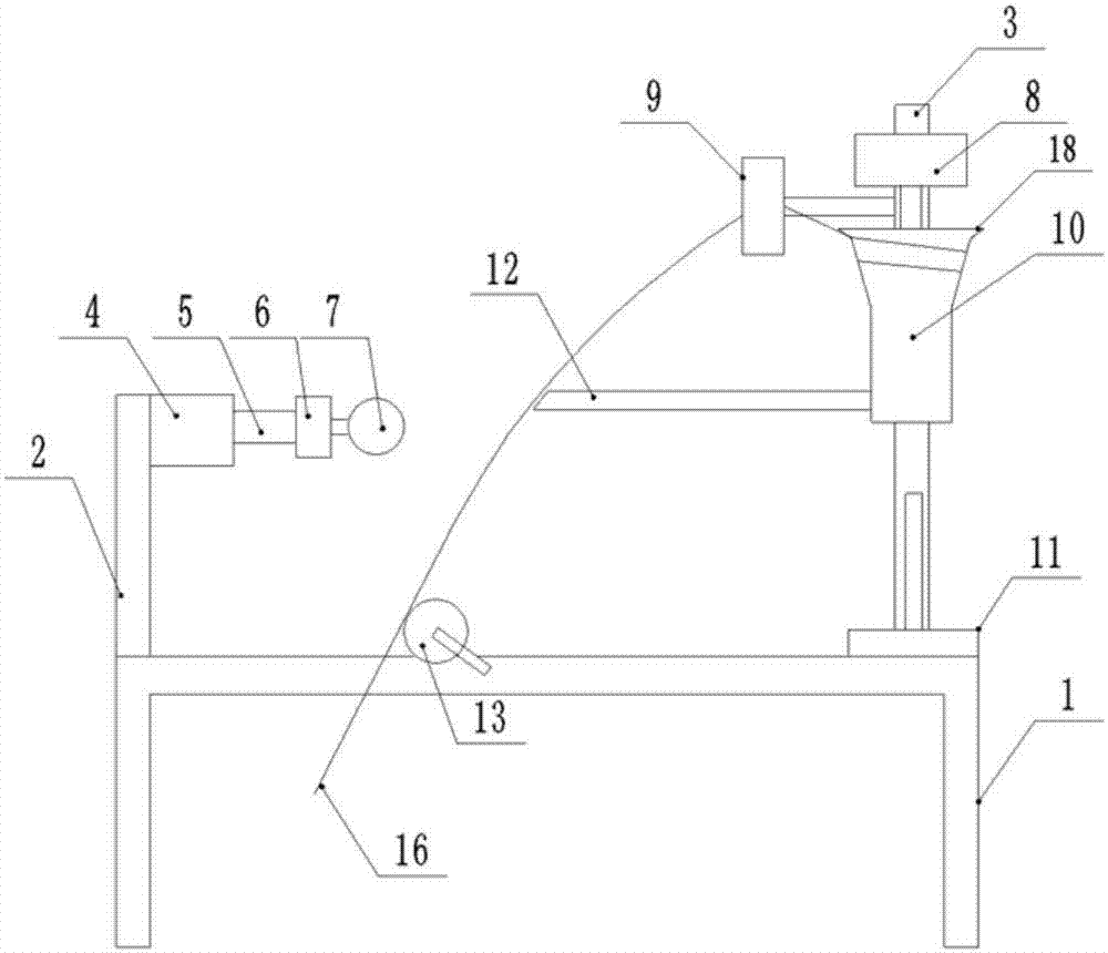
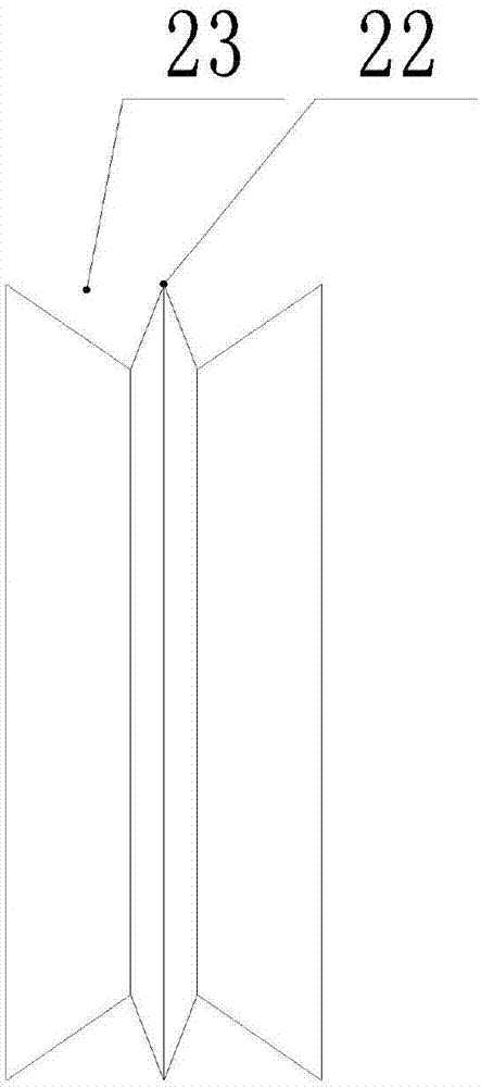
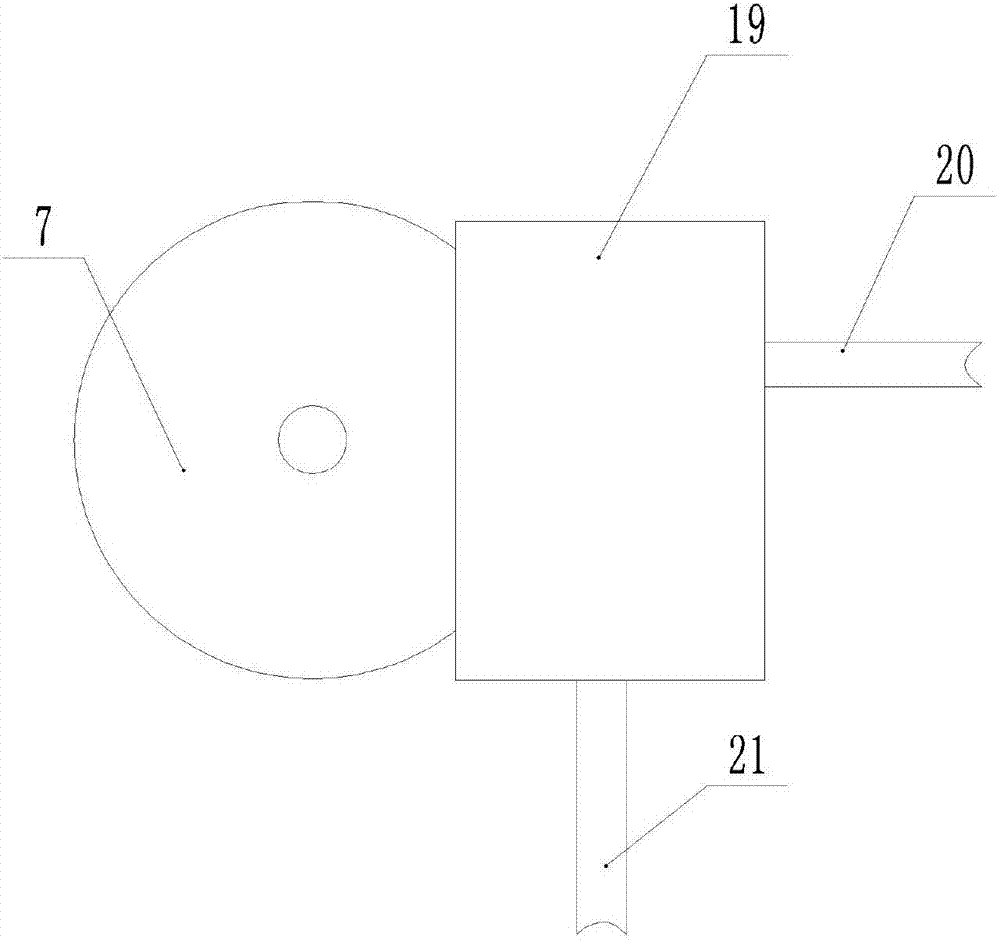
[0024] Such as figure 1 As shown, the waste cable recovery device includes a frame 1, the left end of the frame 1 is fixedly connected with a support rod 2 by welding or bolts, the right end of the frame 1 is welded with a bracket 3, and the cylinder 4 is installed on the upper end of the support rod 2 by welding, The expansion link 5 of cylinder 4 faces rightward, and first motor 6 is welded on the expansion link 5, and cutting knife 7 is fixed by bolt and nut on the output shaft of first motor 6; figure 2 As shown, the cutting knife 7 is provided with an inwardly recessed knife groove 23 along the circumference, and the bottom of the knife groove 23 is processed with an annular blade 22; image 3As shown, the left side of the cutting knife 7 is equipped with an inwardly sunken hot water chamber 19, and the hot water chamber 19 is provided with a hot water tank inwardly. The water pipe 20 and the hot water outlet pipe 21; the upper end of the support 3 is welded with a seco...

Embodiment 2

[0027] Such as Figure 4 As shown, on the basis of Embodiment 1, the left end of the scraper 12 is welded with a horizontal shaft, a support frame 17 is installed on the horizontal shaft, a torsion spring is installed between the horizontal shaft and the support frame 17, and a rotating connection is installed on the support frame. Roll top roller 15, under the action of torsion spring, roll top roller 15 is leaned against on the cable wire 16, when lead moves, can make roll top roller 15 rotate under the frictional force drive of lead wire and roll top roller, can simultaneously The insulating skin that scraper 12 peels off is wound on the volume skin roller 15; Figure 6 As shown, on the upper surface of the winding roller 10 and the right side of the guide wheel 9, the meshing gears are processed, the rotation of the winding roller 10 can drive the guide wheel 9 to rotate, and the sponge is pasted on the inside of the guide hole, and the guide wheel 9 rotates The surface o...


PUM


Abstract

The invention belongs to the technical field of cable waste treatment equipment and particularly discloses a waste cable recovery device. The waste cable recovery device comprises a rack, wherein a support rod is arranged at one end of the rack and a bracket is arranged at the other end of the rack; an air cylinder is arranged at the upper end of the support rod; a first motor is arranged on a telescopic pole of the air cylinder; a cutter knife is arranged on an output shaft of the first motor; a second motor and a guide roller are arranged at the upper end of the bracket; a winding roller isarranged on the output shaft of the second motor; the upper end of the winding roller is in an inverted cone form; a horizontal guide hole is formed in the guide roller; a wire spool opposite to the winding roller is arranged on the rack; a horizontal scraper is arranged in the middle of the bracket; and a wire feeding roller in rotational connection is arranged in the middle of the rack. The waste cable recovery device is mainly used for recovering copper wires in waste cables and wires, so that the problem that the recovery efficiency is reduced due to the fact that the peeled copper wires cannot be automatically wound and collected in the recovery process is solved.

Description

technical field [0001] The invention belongs to the technical field of cable waste processing equipment, and specifically discloses a waste cable recovery device. Background technique [0002] Cables and wires are wire products used to transmit electric energy, information and realize electromagnetic energy conversion. With the rapid development of the communication industry, the simple telephone and telegraph cables in the past have developed into thousands of pairs of telephone cables, coaxial cables, optical cables, and data cables. , and even combined communication cables, etc., the use of cables and wires has brought a lot of convenience to people's lives. [0003] However, with the widespread use of cables and wires, cables and wires have to be replaced with new ones after their service life expires, and a large amount of waste cables and wires will be generated. Recycling waste cables and wires can save a lot of resources. Wrapped with insulation, the insulation need...

Claims


Application Information

Patent Timeline
Patent Type & Authority Applications(China)
IPC IPC(8): H02G1/12
CPCH02G1/1275H02G1/126
Inventor 王健
Owner 宁波得晴电器科技有限公司
Why Eureka
Try Eureka