Petroleum soil cleaning device

A technology for cleaning device and soil, applied in cleaning device, mixer with rotary stirring device, transportation and packaging, etc., can solve the problems of high separation cost, waste of resources, etc., to improve separation efficiency, increase service life, and improve output. The effect of material efficiency

Inactive Publication Date: 2021-12-10
青岛黑铀科技有限公司
View PDF0 Cites 0 Cited by
  • Summary
  • Abstract
  • Description
  • Claims
  • Application Information

AI Technical Summary

Problems solved by technology

[0002] Fiber separation equipment, also known as fiber separation machine, is a waste fiber processing equipment. It uses the difference in specific gravity between waste fiber pulp and impurities to remove light and heavy impurities in waste fiber raw materials. It also has the functions of defusing and screening. The existing All fiber separation uses mechanical separation, which achieves the required effect through a variety of mechanical energy, wastes a lot of resources and high separation cost

Method used


Image

  • Petroleum soil cleaning device
  • Petroleum soil cleaning device
  • Petroleum soil cleaning device

Examples


Embodiment 1

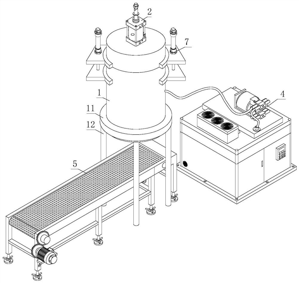
[0039] see Figure 1-Figure 2, a petroleum soil cleaning device, comprising a cleaning tank body 1, an outer hoop ring 11 is sleeved outside the bottom of the cleaning tank body 1, brackets 12 are respectively installed around the bottom of the outer hoop ring 11, and a stirring and separating device is arranged inside the cleaning tank body 1 2. A water injection device 3 is installed above the stirring and separating device 2, a discharge port 13 is provided under the cleaning tank body 1, an oil recovery device 4 is installed at the side end of the cleaning tank body 1, and soil transportation is installed inside the support 12 under the cleaning tank body 1 device 5.

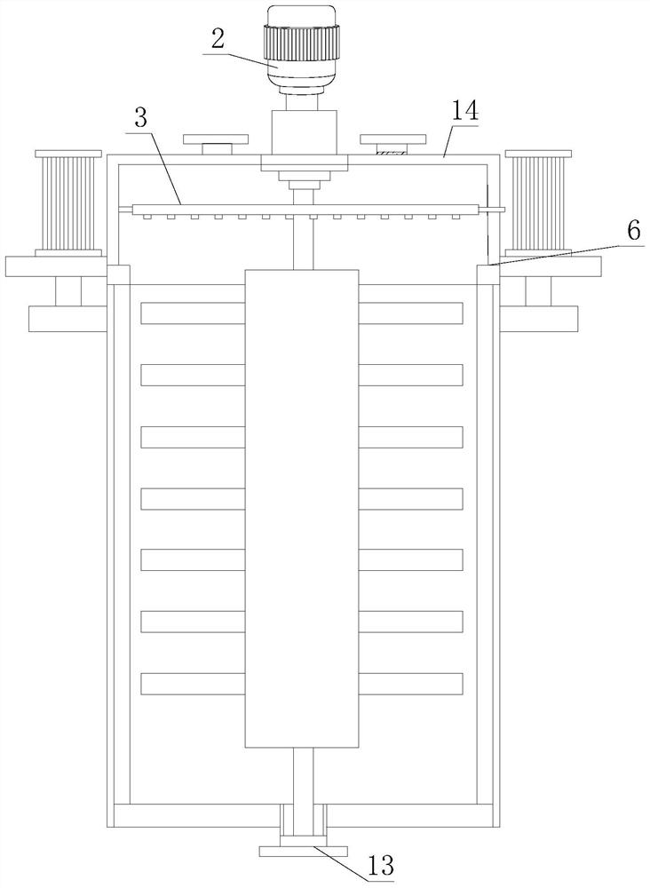
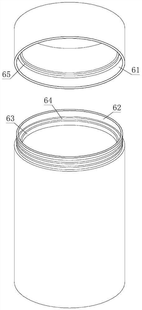
[0040] see image 3 The top of the cleaning tank body 1 is provided with an upper cover 14, and a seal 6 and a lifting device 7 are arranged between the upper cover 14 and the cleaning tank body 1. The seal 6 includes an outer coat layer 61, an inner connection layer 62, a sealing pad seat 63, and a sealing...

Embodiment 2

[0047] see Figure 11 , a petroleum soil cleaning device, comprising a cleaning tank body 1, an outer hoop 11 is sleeved on the outside of the bottom of the cleaning tank body 1, brackets 12 are respectively installed around the bottom of the outer hoop ring 11, and the inside of the cleaning tank body 1 A stirring and separating device 2 is set, and a water injection device 3 is arranged above the stirring and separating device 2. A discharge port 13 is provided under the cleaning tank body 1, an oil recovery device 4 is arranged at the side end of the cleaning tank body 1, and the bottom of the bracket 12 of the cleaning tank body 1 is cleaned. The soil conveying device 5 is arranged inside, and a loam cake 14 is arranged on the top of the cleaning tank body 1, and a sealing member 6 and a lifting device 7 are arranged between the loam cake 14 and the cleaning tank body 1, and the sealing member 6 includes an outer coat layer 61, an inner layer 62, Gasket seat 63, tight join...


PUM


Abstract

The invention discloses a petroleum soil cleaning device, and belongs to the technical field of petroleum soil cleaning, the petroleum soil cleaning device comprises a cleaning tank body, the outer side of the lower part of the cleaning tank body is sleeved with an outer hoop ring, the periphery of the lower part of the outer hoop ring is respectively provided with a bracket, the cleaning tank body is internally provided with a stirring and separating device, and a water injection device is arranged above the stirring and separating device. According to the petroleum soil cleaning device, the interior of the cleaning tank body can be cleaned conveniently, the service life is prolonged, discharging is not affected, meanwhile, a discharging port is prevented from being blocked, the discharging efficiency is improved, petroleum in soil can be separated from the soil conveniently, the separation efficiency is improved, effective separation can be achieved, the soil cleaning efficiency is improved, and the environment is effectively protected; and the soil utilization rate is increased, petroleum can be conveniently recycled, the petroleum utilization rate is increased, resources are saved, adhesion is prevented, the discharging efficiency is improved, the sudden collection efficiency is improved, and soil collection is facilitated.

Description

technical field [0001] The invention relates to the technical field of petroleum soil cleaning, in particular to a petroleum soil cleaning device. Background technique [0002] Fiber separation equipment, also known as fiber separation machine, is a waste fiber processing equipment. It uses the difference in specific gravity between waste fiber pulp and impurities to remove light and heavy impurities in waste fiber raw materials. It also has the functions of defusing and screening. The existing Most of the fiber separation uses mechanical separation, through a variety of mechanical energy to achieve the required effect, a lot of resources are wasted, and the separation cost is high. Contents of the invention [0003] The purpose of the present invention is to provide convenience for cleaning the inside of the cleaning tank, increase the service life, prevent the blockage of the discharge port without affecting the discharge, improve the discharge efficiency, facilitate the...

Claims


Application Information

Patent Timeline
IPC IPC(8): B01D36/00B01F7/18B01F15/00F26B21/00B65G45/12
CPCB01D36/00F26B21/001B65G45/12
Inventor 于蕾
Owner 青岛黑铀科技有限公司
Why Eureka
Try Eureka