Motor and electric tool

A power tool, working technology, applied in the field of power tools, motors that drive power tools to work, and power tools of motors

Inactive Publication Date: 2018-05-01
POSITEC POWER TOOLS (SUZHOU) CO LTD
View PDF6 Cites 6 Cited by
  • Summary
  • Abstract
  • Description
  • Claims
  • Application Information

AI Technical Summary

Problems solved by technology

[0006] The problem with traditional power tools is that each power tool needs to be equipped with modules such as a motor, an energy supply unit, and a control circuit.
[0007] In order to realize the common use of the above-mentioned motors among different power tools, the biggest difficulty lies in that different power tools have different requirements for power, speed, torque, and efficiency. How to achieve high efficiency of the motor under different power, speed, and torque, How to take into account the requirements of the minimum power tool for the working efficiency of the motor, and at the same time realize the problem of ensuring that the motor does not burn out when working on the highest power tool, and how to meet the maximum and minimum speed requirements of different tools

Method used


Image

  • Motor and electric tool
  • Motor and electric tool
  • Motor and electric tool

Examples


Embodiment Construction

[0199] The detailed description and technical content of the present invention are described below with the accompanying drawings, but the attached drawings are only for reference and description, and are not used to limit the present invention.

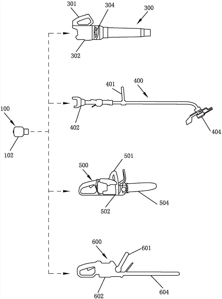
[0200] Such as figure 1 Shown is a schematic structural diagram of an electric tool system in a preferred embodiment. The power tool system includes a power device 100 and at least two tool bodies of the power tool, wherein the power device 100 is detachably installed with the tool bodies of the at least two power tools to provide power for the tool bodies of the at least two power tools. In this embodiment, there are four kinds of tool bodies included in the power tool system, which are respectively a blower tool body 300, a lawnmower tool body 400, a chainsaw tool body 500, and a pruning shears tool body 600. All four kinds of tool bodies are provided with the same interface for installing the power device 100. The aforementioned...


PUM


Abstract

The invention relates to a motor used for an electric tool. The motor comprises a stator, a rotor which rotates relative to the stator, a magnetic pole sheet fixed in the motor, a rotation shaft and astator support used for fixing the stator on the electric motor tool. The motor generates magnetic field after being electrified and acts with the magnetic pole sheet so as to allow the rotor to rotate. The rotation shaft is fixedly connected with the rotor and rotates along with the rotor so as to drive working parts of the electric tool to execute related work. The size of the motor is v, the power of the motor during work is P, and the rated power of the motor is P. The ratio of the rated power of the motor P to the size v of the motor is k, and the k >= 16.5w / cm<3>. According to the invention, by improving the power density of the motor, the size and mass of the motor can be reduced; the size and mass of the electric tool equipped with the motor can be reduced; and the electric tool is portable.

Description

technical field [0001] The invention relates to a motor, in particular to a motor used to drive an electric tool to work. [0002] The present invention also relates to an electric tool, especially an electric tool with a motor that drives the electric tool to work. [0003] The invention relates to a tool body. The invention also relates to an electric tool. Background technique [0004] In the existing motor structure installed in the electric tool, when the rated power of the electric tool is above 900w, due to the motor power P, P=K*D2*L*N, where K is a constant. D is the rotor diameter of the motor, L is the stack length of the stator of the motor, and N is the rotational speed of the motor. It can be seen from the formula that the power output of the motor can be increased by increasing any one of the rotational speed, stack thickness, or outer diameter. After the motor speed N is increased, the motor is subject to a larger centrifugal force, and under the action o...

Claims


Application Information

Patent Timeline
Patent Type & Authority Applications(China)
IPC IPC(8): H02K21/22H02K1/27H02K1/12H02K9/04H02K9/06H02K1/18H02K7/08
CPCH02K1/12H02K1/18H02K1/2786H02K7/083H02K9/04H02K9/06H02K21/22H02K2213/03H02K1/27
Inventor 张伟李伟锋李光
Owner POSITEC POWER TOOLS (SUZHOU) CO LTD
Why Eureka
Try Eureka